background image

HONEYWELL CONFIDENTIAL 


Test Equipment Set Up

:    


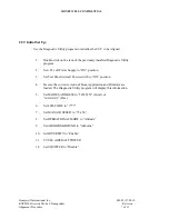
IFR ATC-1400A, S-1403DL Set UP:  
 

1.


S-1403DL set up: 

a.


Set IFR to OCTAL Mode: 

1.


Set menu to “C76”. 

2.


Move cursor to “:HEX” 

3.


Press “ON/CAL” key & toggle to OCTAL. 


b.


Set up for ATCRBS: 

1. 

Set menu to “C10  f01”:ATC (ATCRBS) 


c.


Set up for Long Mode S: 

1. 

Set menu to “C10  f02”:SEQ (Mode S). 

2. 

Press the S menu key on the keypad. 

3. 

Select: S000: D; UF05, PC=0, RR=20, DI=0, SD=100000, 


ADDR=52525252 on the screen.  


2.


S-1400A set up: 

a.


Set the PRF to 100 

b.


Set XPDR Mode switch to “A” 

c.


Set SLS/ECHO  to “-9dBm” 

d.


Set SLS/ECHO switch to “OFF” 

e.


Set the RF signal level to -50dBm 


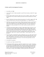
Scope: 

1.


Select channel 2 for observing the IFR detected Video Output (XMTR)

.


2.


Select normal trigger on channel 2. Set the trigger position to 10%. 

3.


Select the Measurement mode and set for Pulse Width, Rise time, and Fall 
time measurements. 


Spectrum Analyzer: 

1.


Set the center frequency to 1090MHz. 

2.


Set the Bandwidth to 3 MHz. 

3.


Set the Span to 1 GHz (normal operation). 

4.


Set the Sweep to 10 seconds 


NOTE: 

Prior to Alignment, perform a visual inspection of all the test equipment. 
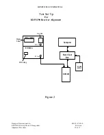
Verify all connections are made per the Alignment Setup diagrams. 
Verify all cables and fixtures are in good repair and free of any defects. 

Honeywell International Inc. 

001-05117-0010 

KXP2290 Diversity Mode S Transponder 

Revision   - 

Alignment Procedure 

6 of 11 

Summary of Contents for KXP2290

Page 1: ......

Page 2: ...ed duplicated or disclosed for any purpose without prior written permission of Honeywell International Inc All Rights Reserved Copyright 2005 Honeywell International Inc REVISION HISTORY Revision PRN CO Description Date 768843 Initial Release See Cover Page Honeywell International Inc 001 05117 0010 KXP2290 Diversity Mode S Transponder Revision Alignment Procedure 2 of 11 ...

Page 3: ...r and transmitter power levels are measured at the antenna end of a nominal 2dB loss coaxial cable 1 KXP2290 Manual Test Panel KPN 071 00224 0020 2 IFR ATC 1400A S 1403DL with MLD or 1403DL without MLD DME Transponder test set 3 Oscilloscope Tektronix TDS 320 350 380 3054B 520 540C or equivalent 4 Digital multi meter 3 digits Fluke 8010A or equivalent 5 Power Supply 0 to 30 Volts 5 Amps or equival...

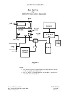
Page 4: ...dB 50ohm load IFR 1400A KXP2290 Computer Bench Test Box Power Supply XMTR Figure 1 Notes 1 The IFR TX detector XMTR Output is connected to a channel of the scope with a 50 ohm load 2 The RF power to spectrum analyzer should have a 20dB pad to spectrum analyzer input port Honeywell International Inc 001 05117 0010 KXP2290 Diversity Mode S Transponder Revision Alignment Procedure 4 of 11 ...

Page 5: ...p_Diag exe file onto desktop Double click icon to activate program Test Panel Set Up 1 Connect a RS232 cable from COMM Port of the computer to the RS232 DIAG input on the Test Panel KPN 071 00224 0020 2 Connect Bench Test Cable KPN 200 10336 0050 or 200 10336 0120 from the Test Panel to the KXP2290 UUT 3 Set Test Panel switches in the following positions a Air Gnd OFF b Standby OUT c UUT Strap XPD...

Page 6: ... signal level to 50dBm Scope 1 Select channel 2 for observing the IFR detected Video Output XMTR 2 Select normal trigger on channel 2 Set the trigger position to 10 3 Select the Measurement mode and set for Pulse Width Rise time and Fall time measurements Spectrum Analyzer 1 Set the center frequency to 1090MHz 2 Set the Bandwidth to 3 MHz 3 Set the Span to 1 GHz normal operation 4 Set the Sweep to...

Page 7: ...ure the correct revision of Boot Application and Firmware are loaded The Diagnostic Utility program will display this information 5 Set MODE S ADDRESS to 52525252 Octal or AAAAAA Hex 6 Set 4096 CODE to 7777 7 Set MAX AIR SPEED to 75 150 8 Set OPERATIONAL MODE to Altitude 9 Set AIRBORN GROUND to Airborne 10 Set DIVERSITY to Enable 11 CYCLE AIRCRAFT POWER 12 Set SQUITTER to Disable Honeywell Interna...

Page 8: ...se Fall time should be greater than 50ns and less than 170ns Make minor readjustments to C27 C44 and C26 on the TX Final board as necessary to bring the pulse Rise and Fall times within specifications Check the power output on the IFR display It should be greater than 125W minimum 7 Set the scope delay to approximately 20 5usec and adjust as necessary to observe the last pulse of the TX pulse trai...

Page 9: ... 7 to 23 Mhz 20dB or more Increase span to 200Mhz Set RES BW to 3Mhz 23 to 78 Mhz 40dB or more Increase span to 500Mhz 78Mhz 60dB or more 14 Make slight adjustments if necessary to C26 C27 and C44 on the TX Final board to bring the side lobes within specifications 15 Set the IFR back to ATCRBS 16 Set the Spectrum analyzer Span to 1Ghz and the RES BW back to 3Mhz 17 Repeat all TX Pulse Spectrum tes...

Page 10: ...lignment IFR S 1403DL PRF setting RF Port B IFR 1400A KXP2290 Computer Bench Test Box POWER SUPPLY RF Port A Key Pad Display Screen Figure 2 Honeywell International Inc 001 05117 0010 KXP2290 Diversity Mode S Transponder Revision Alignment Procedure 10 of 11 ...

Page 11: ...ust R2212 on the KXP2290 Receiver Board to obtain a 50 to 70 reply 6 Set IFR RF Level to 74dBm 7 Observe the IFR for a 99 to 100 ATCRBS reply 8 Connect a 2dB loss RF cable from IFR antenna port A to the KXP2290 Top Antenna port J3 The KXP2290 Bottom Antenna port J2 is not connected to IFR at this time 9 Set IFR RF level to 75dBm 10 While observing the IFR for ATCRBS reply adjust R2211 on the KXP22...

Reviews: