background image

EN2C-0111SZ20 R0202

6

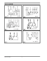
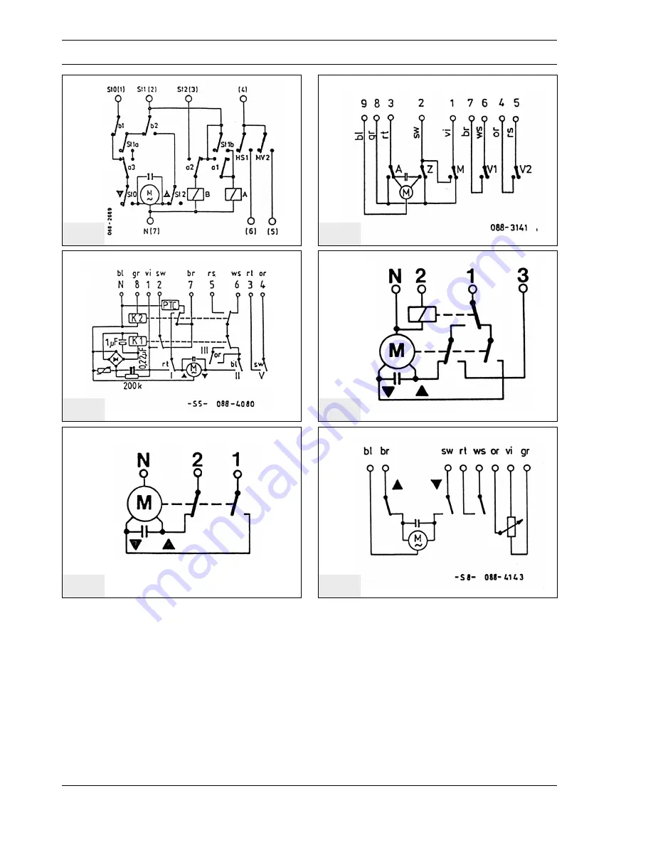
CIRCUIT DIAGRAMS

S4

S3

S5

S6

S7

S8

Summary of Contents for LKS 131

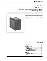
Page 1: ...es 2 TECHNICAL DATA Specification 3 Dimensional drawings 4 INSTALLATION AND OPERATION Installation and final checkout 5 Circuit diagrams 6 VARIOUS Standards and approvals 7 Ordering information 7 Accessories 7 APPLICATION The LKS 131 air damper actuator is designed to be fitted to multi stage or modulating oil and gas burners with fully closed position ...

Page 2: ...iants clockwise or counter clockwise rotation with integrated electronic circuitry shaft version DESCRIPTION positionatwhichoneofthelimitorauxiliaryswitchesoperates can be adjusted steplessly within the operating range using the associated cam disc Spindle driven cams which can be adjusted with a screwdriver are available FEATURES Internal position indicator Easily adjustable limit and auxiliary s...

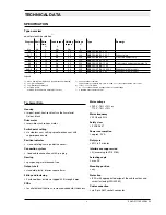
Page 3: ...nection with 9 pin plug Gearing spur gearing maintenance free Output shaft standard plastic interior square 8 mm Fitting and fastening Fastened from inside via tapped M 5 through holes PCBs for all electrical functions increased conductor thickness Mains voltage 230 V 15 10 or 110 V 15 10 Mains frequency 50 Hz or 60 Hz Safety class II VDE 0631 Power consumption approx 9 VA Duty cycle 50 in 2 minut...

Page 4: ...5 38 sec for 90 Limit and auxiliary switches max 7 operation with adjustable cam discs cams coloured in normal way blue fully closed position orange low load red high load black spare switches for additional functions switching voltage AC 24 230 V switching capacity with inductive loads 250 VA Ambient temperature operation 0 60 C transport and storage 20 60 C Condensation icing and exposure to wat...

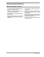
Page 5: ... separately and as remotely as possible from the device and other cables Carefully check all cabling and wiring prior to commissioning Disconnect the actuators completely from the power supply when working close to terminals and connections Screw the housing cover securely in place to provide shock hazard protection on the actuator and all electrical connections Electromagnetic emissions must be c...

Page 6: ...EN2C 0111SZ20 R0202 6 CIRCUIT DIAGRAMS S4 S3 S5 S6 S7 S8 ...

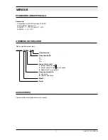
Page 7: ...gle 6 Special shaft e g round 6 Direction of rotation A clockwise B counter clockwise Model Series Not for creation of new type Conformity In accordance with EU Directives 73 23 EU and 93 68 EU Conforms to EN 60730 1 1991 A1 and A11 1991 EN 60730 2 5 1991 ORDERING INFORMATION Special versions with potentiometer on request STANDARDS AND APPROVALS ACCESSORIES VARIOUS ...

Reviews: