PW7K1ICE Wiring and Setup
Communication Wiring
PW7K1ICE Installation and Configuration Guide
, Document 800-26497
23
•
Power is supplied via the Ethernet connection using PoE or PoE+
.
• Or Local 12VDC power supply, TB4-3 (VIN), TB4-4 (GND).
2.9 Communication Wiring
The PW7K1ICE (LP1501) controller communicates to the host via the on-board 10-
BaseT/100Base-TX Ethernet interface (port 0).
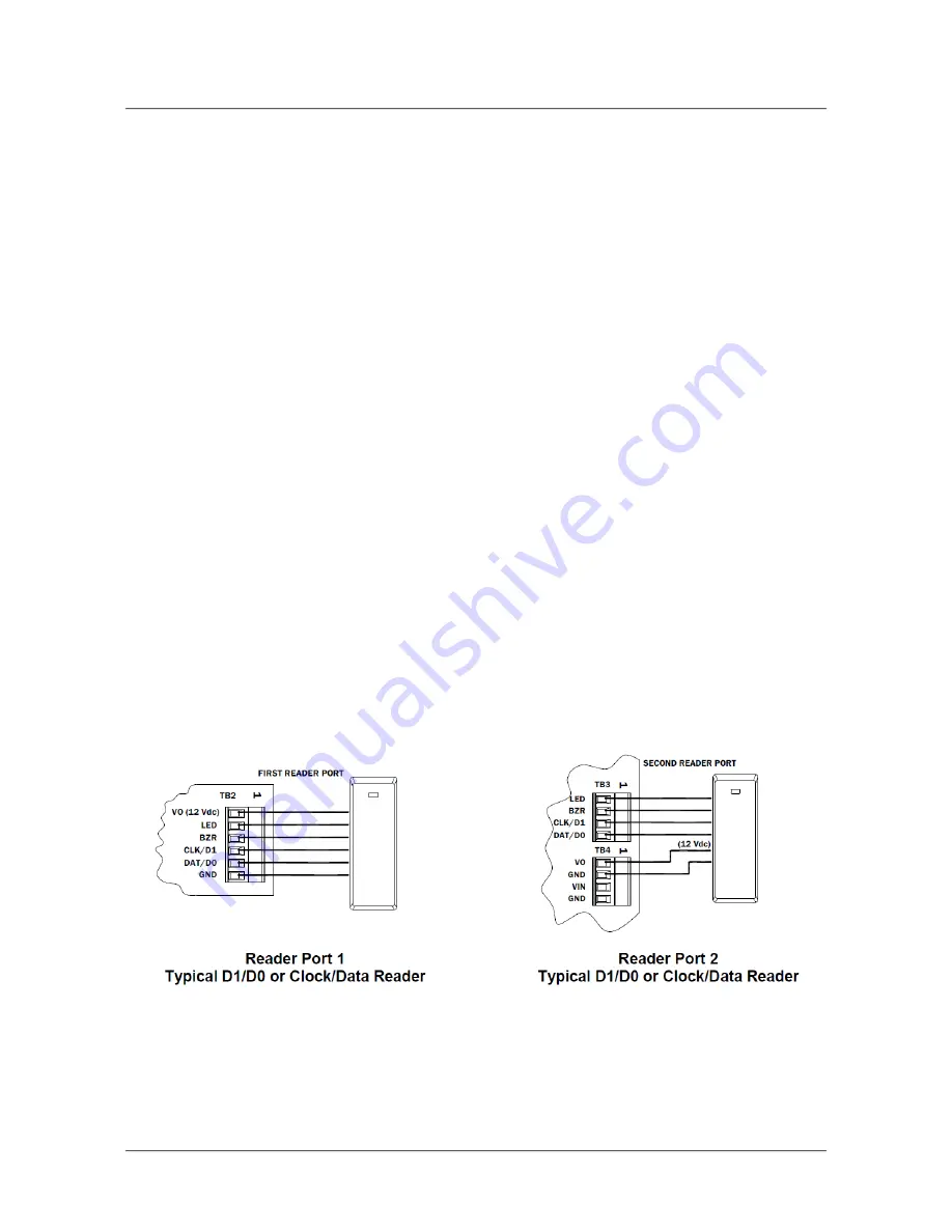
2.10 Reader Wiring
Reader port 1 supports TTL (D1/D0, Clock/Data), F/2F, or 2-wire RS-485 device(s).
Reader port 2 supports TTL (D1/D0, Clock/Data), or F/2F. Power to reader port 1 is
12 VDC at 300 mA maximum. The reader connected to reader port 2 may be powered
from the 12 VDC auxiliary power supply output; TB4-1 and TB4- 2. Readers that
require different voltage or have high current requirements should be powered
separately. Refer to the reader manufacture specifications for cabling requirements. In
the 2-wire LED mode, the buzzer output is used to drive the second LED. Reader port
configuration is set via the host software.
Reader port 1 can support up to eight 2-wire RS-485 remote serial I/O devices
using MSP1 protocol or up to two OSDP devices. If two OSDP devices are
used, reader port 2 will not support a third reader. If only one OSDP device is
configured, then reader port 2 is available for a second reader. The maximum
cable length is 2000 ft. (610 m). Do not terminate any RS-485 devices
connected to reader port 1.
Figure 2-3: Reader Wiring Diagram


