LTE-X Series Installation and Setup Guide
– 5 –
4.
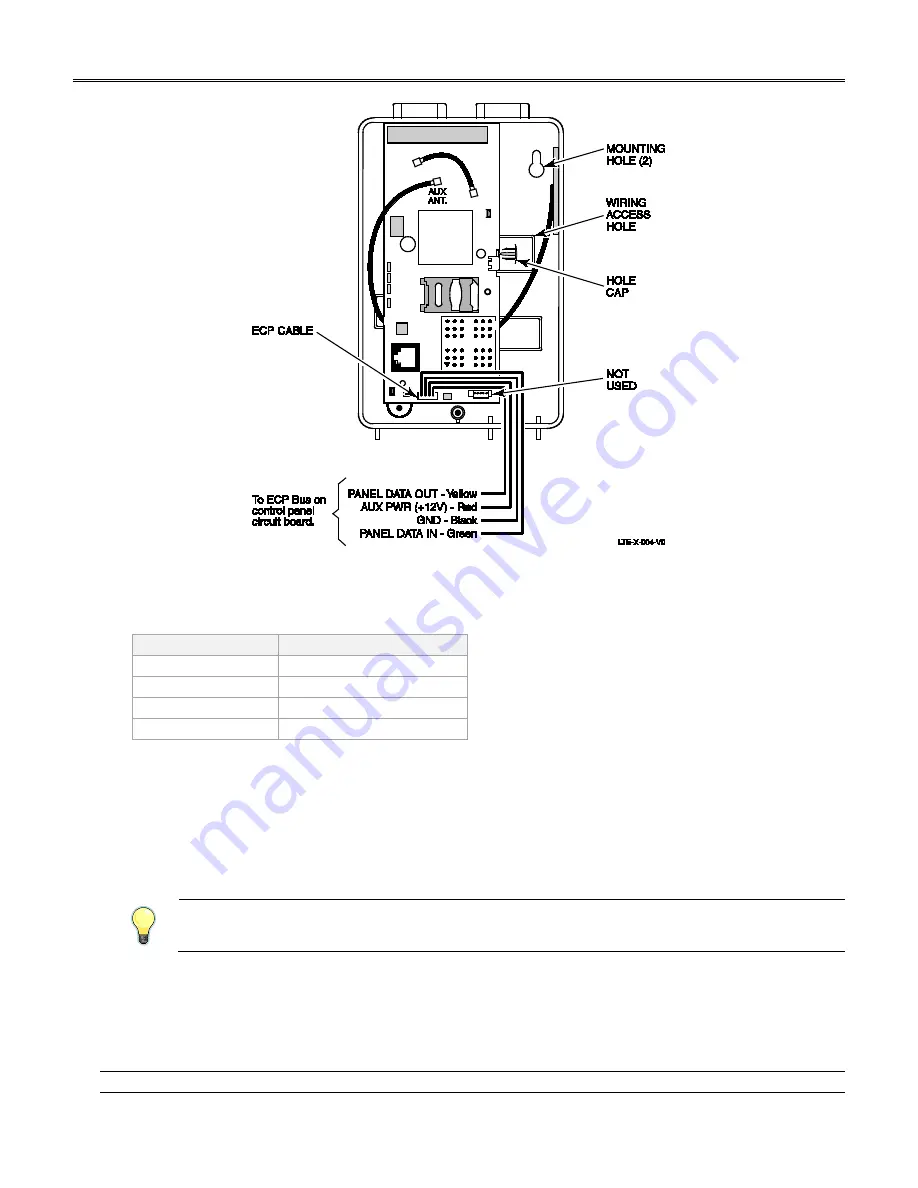
Connect the ECP cable to the communicator circuit board. When mounting the communicator off the cabinet, the
length of the supplied ECP cable will have to be spliced to a four-wire extender cable.
Ensure the splices are
located within the communicator's enclosure.
Use the table below to determine the minimum wire gauge for the extender cable.
Minimum Wire Gauge
Distance from Control Panel
#22
75 ft (23m)
#20
120 ft (37m)
#18
170 ft (52m)
#16
270 ft (82m)
5.
Route the wires through the rear wiring access hole or bottom knockout on the communicator. Continue routing
the wiring to the control panel. A control panel knockout that is presently used can be utilized, however DO NOT
utilize a control panel knockout that is being used for primary power.
6.
Refer to the installation guide for the control panel, and complete the ECP cable wiring.
7.
Secure the wiring with ties as necessary.
Programming the Module
The LTE-X requires an AlarmNet account. For new installations, please obtain the account information from the central
station prior to programming.
You can program the communicator by one of the following methods:
•
Using the AlarmNet 360 website.
•
Using the 7720P Programming Tool.
•
Using the control panel's programming mode (for panels that support this option) to access the communicator's
programming.
NOTE:
The prompts in this document reflect use of the 7720P Programming Tool.


