background image


– 16 – 

-.

-.

-.

-.

&'

General Information 

3* @&&@&@& A &&

 ! 

;

(!*

! :8&;&  &&' 

H.%*@ &


  *

! ) ) &&&8 


 & 

System Can Be Armed 

! 8&H.%&A )&&&&@

C8&D&&*&    <  

Summary of Contents for LYNX Touch L5210 Series

Page 1: ... 800 19975 12 14 Rev A LYNX Touch L5210 Series ...

Page 2: ...icating bus if Honeywell has not approved such device for use with your security system Use of any such unauthorized device may cause damage or compromise the performance of your security system and affect the validity of your Honeywell limited warranty When you purchase devices that have been manufactured or approved by Honeywell you acquire the assurance that these devices have been thoroughly t...

Page 3: ... 3 0 12 1 3 4 5 1 4 6 1 7 8 4 2 2 22 8 9 2 4 8 4 1 9 8 2 1 1 4 8 2 ...

Page 4: ... 4 ...

Page 5: ... or stolen another person can compromise your security system Immediately notify your Dealer Installer of a lost or stolen key fob The Dealer Installer will then remove the key fob programming from the security system 3 8 0 8 8 0 1 B 2 4 B B 8 3 2 8 7 8 1 1 C B D B 8 2 8 8 E 4 4 8 E 9 8 E 9 Zones F GA G 0 0 A A 1 ...

Page 6: ...es 2B C 7 D 1 8 Alarms 9 H I B A B A 9 A A 8 Important Note If your system is equipped to report alarms over the internet via a WiFi Communications module your router must remain powered on at all times Ask your Installer about this feature for additional information Two Way Voice Feature B ...

Page 7: ... 7 LYNX Touch False Alarm Prevention Features H I 0 5 0 0 5 H C 0 D 0 5 0 5 0 0 0 0 0 0 8 8 C 9 D 8 0 C D 3 C D ...

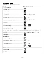
Page 8: ...is not required if Quick Arm is active Disarm system and silence alarms Disarm Code Note During Entry Delay or when an Alarm Condition exists the LYNX Touch can be disarmed by entering the User Code Entering the OFF key is not required Arm Instant Set Delay tab to Instant then Arm STAY or AWAY Bypass a zone s Zones SYSTEM SETTINGS Adjust Volume or Brightness Settings Restore unmute user announceme...

Page 9: ... Master Code can be used to add delete a User Perform Tests Test Applicable Test icon View System Events Events Program edit or delete Reminders Reminders HOME AUTOMATION If equipped Operate Garage Door Automation Manually operate Z Wave Devices Automation OR 68 OR OR Switches Thermostats Locks Water Valves Set Scenes Schedules or Rules OR Run Scenes Automation OR OR Scenes Schedules Rules ...

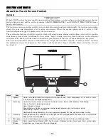
Page 10: ... Armed Green Blinking System is disarmed and not ready to be armed a fault or alarm exists Red Blinking System is in Alarm Red Green Blinking alternately System programming mode OR Two way voice mode is active 3 Panic key When depressed for 4 seconds the virtual panic icons are displayed on the touch screen Internal Red LED is lit in normal conditions 4 Microphone Used to record personal messages ...

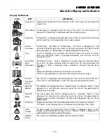
Page 11: ...ed when a window or entry exit fault has been detected OR Displayed alternately with the alarm bell icon and Alarm Alarm is also displayed in a red status bar along the top of the screen Fire OR Fire Alarm 95 Fire The fire icon is displayed with alternating text Fire and Fire Alarm 95 Fire Fire Alarm is also displayed in a red status bar along the top of the screen Alarm 96 Medical The Medical ico...

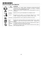
Page 12: ...system has lost AC power Ready To Arm System Trouble is displayed in a yellow status bar along the top of the screen Automation Displayed when the system has detected a Z Wave Device Failure Fault Main Garage Door Displayed when the Garage Door has been opened Ready To Arm Fault is displayed in a yellow status bar along the top of the screen Applicable Zone Number Not applicable Displayed in the u...

Page 13: ...speaker To adjust the volume select More on the home Screen and then select Settings Adjust the volume using the slide shown on the Settings screen and then select Save to accept Home Screen J C D J C D Note Access to Text Messages Weather News and Traffic and other web content requires Total Connect Services Ask your Installer which of these features have been programmed in your system L 4 L 4 5B...

Page 14: ...en Tools Provides access to Master User Programming Menus Master User Code required for access Arm Stay Used to Arm the system in Stay mode Displayed on both pages of the Security screen Settings Provides access to Touch Screen functions including Brightness Volume Voice Chime and Ringer Zones Provides access to Zone information and options Delay Instant Toggles between Delay and Instant to enable...

Page 15: ...ter User to Test the system Keypad Allows Master user to enroll and view information associated with Mobile Device s Date Time Used to program Date and Time Reminders Allows Master User to add or remove local and Follow Me reminders Slide Show Allows Master User to program screensaver options WiFi Config Provides access to WiFi configuration screen Requires the installation of WiFi Communications ...

Page 16: ... 16 General Information 3 A 8 H 8 System Can Be Armed 8 H A C8 D ...

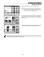
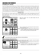
Page 17: ...Arm Arm the system in Stay mode Enter Code Cancel Quick Arm 2 3 1 5 6 4 0 8 9 7 Clear 5200 100 015 V0 2 Enter a valid User Code OR If Quick Arm has been enabled select the Quick Arm icon Note If a valid user code is not entered or the Confirm icon has not been selected within 10 seconds the system returns to the security screen and it will not be armed Armed Stay Exit Now Exit now 28 seconds 5200 ...

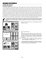
Page 18: ... for servicing of the entry exit zones or to turn off this feature if a check condition on entry exit zones occurs Arming in Night Stay Mode 7 E 0 J 0 A 8 9 A H When NIGHT STAY mode is on the selected interior zones are armed and cause an alarm if anyone enters those areas e g waking in the middle of the night To avoid sounding an alarm you must disarm the system before any activity takes place in...

Page 19: ...seconds 5200 100 126 V0 Phone More Message Zones Disarm Restart 10 18 AM June 8 2010 System 3 The system beeps three times and announces Armed Night Stay Exit Now The exit delay screen is displayed If programmed the display counts down the time remaining in the exit delay Armed Night Stay 5200 100 127 V0 Phone More Message Zones Disarm 10 18 AM June 8 2010 System 4 At the end of the exit delay the...

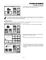
Page 20: ...V0 Cancel Quick Arm 2 Enter a valid User Code OR If Quick Arm has been enabled select the Quick Arm icon The system beeps two times and announces Armed Away Exit Now The exit delay screen is displayed If programmed the display counts down the time remaining in the exit delay in seconds Note If a valid user code is not entered or the Confirm icon has not been selected within 10 seconds the system w...

Page 21: ...10 18 AM June 8 2010 Zones 1 Select the Arm Away icon the system displays a keypad Ready To Arm Arm the system in Away mode Silent Exit Enter Code 2 3 1 5 6 4 0 8 9 7 Clear 5200 100 018 V0 Cancel Quick Arm 2 Select the Silent Exit button If enabled the Silent Exit button turns green Enter a valid User Code OR If Quick Arm has been enabled select the Quick Arm icon 5200 100 019 V0 Armed Away Exit N...

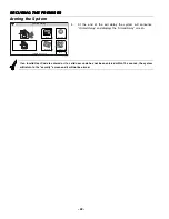
Page 22: ...10 System 4 At the end of the exit delay the system will announce Armed Away and displays the Armed Away screen If an invalid User Code is entered or if a valid user code has not been entered within 10 seconds the system will return to the security screen and it will not be armed ...

Page 23: ...Screen The icon toggles and Instant is displayed 2 Arm the system in the Stay or Away mode normally Note The entry delay time is eliminated when Instant is selected Quick Exit 0 C 0 D B 0 B 0 0 Armed Stay 5200 100 021 V0 Phone More Message Zones Quick Exit Disarm 10 18 AM June 8 2010 System 1 Select the Quick Exit icon to restart the exit delay Note Quick Exit is active in Away mode when Auto Stay...

Page 24: ...m Armed 0 0 C8 D 0 0 B Armed Stay Exit Now Exit now 28 seconds 5200 100 016 V0 Phone More Message Zones Disarm Restart 10 18 AM June 8 2010 System Exit Alarms A 0 9 0 0 A 0 0 C A A 0 A C D 8 C D 0 A G 0 G C 0 G A A C D 8 C D C G C D A A C D 8 C D 0 0 A 0 5 0 0 0 B ...

Page 25: ...45 60 90 seconds 2 minutes None 15 30 45 60 90 seconds 2 3 4 minutes 1 None 15 30 45 60 90 seconds 2 3 4 minutes 2 8 79 5 0 None 15 30 45 60 90 seconds 2 minutes None 15 30 45 60 90 seconds 2 minutes 1 None 15 30 45 60 90 seconds 2 minutes ...

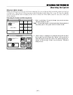
Page 26: ...m icon has not been selected within 30 seconds the system returns to the security screen and it will not be disarmed If an invalid User Code is entered system will return to the Security Screen Disarming the System During Entry Delay Armed Stay Disarm Now Enter Code Cancel Disarm Now 2 3 1 5 6 4 0 8 9 7 Clear 5200 100 023 V0 ARMED READY Upon entering the premise when the system is armed the contro...

Page 27: ...d user code is not entered before the programmed entry delay occurs the system remains in alarm mode Alarm Cancel 5200 100 089 V0 Alarm 2 Front Door Phone More Message Zones Disarm 4 43 PM August 11 2011 System 2 Alarm Cancel is displayed in a red band along with the zone that caused the alarm Select the Disarm icon and enter a valid code again to clear the alarm The system beeps once returns to t...

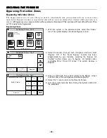
Page 28: ...ct the zone s that you wish to bypass and then select Bypass OR if the Force Bypass feature has been programmed by your Installer selecting the Bypass All Faulted button allows you to bypass all faulted zones excluding Panic Fire or CO zones The system displays a keypad Not Ready to Arm Fault Bypass Selected Zones Enter Code Cancel 5200 100 083 V0 2 3 1 5 6 4 0 8 9 7 Clear 3 Enter a valid Code The...

Page 29: ...to scroll to additional pages and view the zone status 3 If you select the Select All button it scrolls through the following Select All Select Alarm Select Trouble Select Fault and Select Bypassed The system displays the associated zones Note If one or more zones has been bypassed the Clear Bypasses button will be highlighted Ready To Arm Bypass 5200 100 030 V0 99 Police 95 Fire 96 Medical 2 Fron...

Page 30: ... D 3 5 0 C D C D C D E C D Activating a Panic Alarm Ready To Arm 5200 100 031 V0 Police Fire Medical 1 With the system in the disarmed or armed state depress and hold the Panic key until the system displays the Panic screen approximately 3 4 seconds 2 Touch the desired panic icon on the screen 3 If applicable the alarm sounds and the associated icon is displayed Fire Alarm Fire Alarm 95 Fire Enter...

Page 31: ...rns green When On is selected the Chime mode will be active 3 Select the Save button to save your new settings 4 Select the 2 icon to return to the Security Screen Selecting Chime Sounds Armed Stay 5200 100 021 V0 Phone More Message Zones Quick Exit Disarm 10 18 AM June 8 2010 System 1 With the system in the disarmed state select the Zones icon from Security Screen The system displays the Zones sc...

Page 32: ...tem displays the Keypad screen Note The Settings Screen display is variable dependent upon the features that have been programmed in your system Ready To Arm Chime Ringer Voice Brightness Volume 5201 100 004 V0 Save Clean 2 Select the Voice icon The system will toggle between Off and On and when selected the button turns green When On is selected the Voice mode will be active 3 Select the Save but...

Page 33: ...e second page of the Security Screen The system displays the Keypad screen Ready To Arm Program the system Enter Code Cancel 5200 100 035 V0 2 3 1 5 6 4 0 8 9 7 Clear 2 Enter your 4 digit Master User Code The system displays the Master User programming screen WiFi Config Date Time Ready To Arm Events Back Reminders Keypad Users 5200 100 036 V0 Slide Show Test 3 Select the Users icon The system dis...

Page 34: ...V0 Master Thomas Guest Edit Add New Delete Duress 8 Enter the 4 digit code for the new User followed by Done The system returns to the Users Programming screen and the new User is displayed and along with 9 If a Z Wave door lock is installed select the Z wave Lock Control key to enable the User The system toggles between No and Yes When Yes is selected the User Code will be synchronized with all e...

Page 35: ...ders Keypad Users 5200 100 036 V0 Slide Show Test 3 Select the Users icon The system displays the Users screen Ready To Arm 5200 100 041 V0 Master Thomas Guest Edit Add New Delete Duress 4 Select a User Name and then select Edit or Delete If you are editing user information proceed to step 5 If you are deleting a user proceed to step 8 Ready To Arm 5200 100 039 V0 A Q User3 Z S W L O P M K I N J U...

Page 36: ...ode Done 7 If desired enter a new 4 digit code for the selected User followed by Done The system returns to the Users screen 8 Select Yes or No when the confirmation screen is displayed then proceed to step 9 9 Select the 2 icon to return to the Master User screen ...

Page 37: ...pear and displays all events 5200 100 043 V0 Sun Jun 13 2010 15 08 Disarmed User 2 E 441 Sat Jun 12 2010 11 15 Armed Stay User 1 R 441 Sat Jun 12 2010 11 08 Burglary Bypass Zone 3 E 570 Sat Jun 12 2010 10 15 Disarmed User 1 E 401 Fri Jun 11 2010 18 08 Armed Away User 2 R 401 Fri Jun 11 2010 12 10 Disarmed User 3 E 441 Fri Jun 11 2010 11 08 Armed Stay User 2 R 441 Fri Jun 11 2010 10 15 Burglary Byp...

Page 38: ...g 184 Seconds Message 1 Stopped Record Delete Play 2 Select Record the system sounds a single tone Speak into the microphone and record your message 3 When you are finished recording your message select Stop 4 To listen to the message select Play 5 If you wish to delete the message select Delete 6 Record additional messages as required 5200 100 047 V0 Message 1 2 48 PM September 1 2010 Message 2 5...

Page 39: ... select Stop If Stop is not selected the system continues to play the remaining messages 4 When you have finished listening to the messages select 2 The system returns to the Security Screen Deleting Messages 5200 100 047 V0 Message 1 2 48 PM September 1 2010 Message 2 5 09 PM September 5 2010 Add New Delete All Play Ready To Arm 1 At the Message screen select Delete All The system deletes all mes...

Page 40: ... upon the features that have been programmed in your system Ready To Arm Chime Ringer Voice Brightness Volume 5201 100 004 V0 Save Clean 2 Increase or decrease the Display Brightness or the System Volume by using the sliding adjustment from left decrease to right increase 3 Turn the Voice Chime or telephone Ringer On or Off by selecting the appropriate icon The system toggles between On and Off an...

Page 41: ...ar 2 Enter your 4 digit Master User Code The system displays the Master User programming screen WiFi Config Date Time Ready To Arm Events Back Reminders Keypad Users 5200 100 036 V0 Slide Show Test 3 Select the Date Time icon The Calendar screen will appear 5200 100 048 V0 THU SUN WED 3 2 SAT 6 FRI 5 TUE MON 1 18 17 20 19 16 14 15 25 24 27 26 23 21 22 30 28 29 11 10 13 12 9 7 8 June 2010 4 Save Re...

Page 42: ...e correct time zone 11 Select Day Light Savings Time The system toggles between Yes and No Note The start month week and end month week are default programmed to March Second and November First respectively Steps 13 to 16 should only be performed if you wish to change those entries If you are not changing the defaults advance to step 17 Ready To Arm 5200 100 051 V0 January February March April May...

Page 43: ...e complete Note When entering the country use the following codes United States US Canada CA When entering the State or Province be sure to use the proper 2 character State Possession or Province Territory abbreviation For a list of US State Possession standard abbreviations go to http pe usps com text pub28 28apb htm For a list of Canadian Province Territory standard abbreviations go to http pe u...

Page 44: ...ike 71 Mostly Sunny F Automation Ready To Arm 1 With the system in the disarmed state select the Automation icon from the Home Screen The system displays the first page of the Automation screen Select the select the T icon to advance to the second page of the Automation screen 5200 100 053 V0 Garage door setup Tools Rules Schedules Scenes Ready To Arm 2 Select the Schedules icon The system display...

Page 45: ... selected in Step 6 and the Frequency selected in step 7 or if Scene is selected proceed to Step 13 Once Start Time End Time Date Daily Start Time End Time Weekday Start Time End Time Weekly Start Time End Time Day of the Week Monthly Start Time End Time Day of the Month 10 Select Rules then select a Rule from the displayed list Rules 1 through Rules 20 11 Enter a Start Time and End Time on the di...

Page 46: ... steps as noted above in the programming a Scheduled Function section to edit and save your changes Deleting a Scheduled Function Ready To Arm 5200 100 084 V0 Auto Arm Daily Edit Delete Add New Schedule 1 Auto Stay 1 At the Schedules screen select the Schedule you wish to delete Note Rules 21 40 are only accessible through TotalConnect Service 2 Select the Delete button A confirmation screen will ...

Page 47: ...t trouble or alarm as selected Programming Rules 5200 100 001 V0 Video Notices Traffic Security News 5 Day Forecast 2 68 35 1 F PM October 1 2013 Feels Like 71 Mostly Sunny F Automation Ready To Arm 1 With the system in the disarmed state select the Automation icon from the Home Screen The system displays the first page of the Automation screen Select the T icon to advance to the second page of th...

Page 48: ...Scene was selected refer to the Home Automation Guide P N 800 19979 for information Ready To Arm 5200 100 062 V0 Name Save Type Trigger Output 01 Start Zone Type Not Used Start System Operation Not Used Action None Stop Zone Type Not Used Stop System Operation Not Used 7 Select Action Dependent upon the Type selected previously the system scrolls between several options None Permanent On On for 2 ...

Page 49: ...tions as step 10 Ready To Arm 5200 100 063 V0 Save Zone Number Operation Not Used 12 Select Zone Number Operation The system toggles between the following options Not Used Fault Trouble Alarm Notes 1 For Fault the following zone types should not be used General Monitor General Response Resident Monitor and Resident Response 2 When a zone has been deleted please verify the programming selection for...

Page 50: ...re only accessible through TotalConnect Service 2 To delete the rule select the Delete button To edit the rule select the Edit button and proceed to step 3 Ready To Arm 5200 100 066 V0 Name System Armed Save Type Message to phone 1 01 Start Zone Type Not Used Start System Operation Armed Stay Action Send Stop Zone Type Not Used Stop System Operation Disarm 3 Select the field that you wish to edit ...

Page 51: ...ram the system Enter Code Cancel 5200 100 035 V0 2 3 1 5 6 4 0 8 9 7 Clear 2 Enter your 4 digit Master User Code The system displays the Master User programming screen WiFi Config Date Time Ready To Arm Events Back Reminders Keypad Users 5200 100 036 V0 Slide Show Test 3 Select the Reminders icon The system displays the Reminders screen Ready To Arm Save 5200 100 045 V0 No items to display Add New...

Page 52: ...toggles between No and Yes If yes is selected the record reminders screen appears 9 Select the Record button and record your reminder When you are finished select the Stop button followed by the 2 button The system returns to the Reminder programming screen Ready To Arm Save 5200 100 071 V0 Start Time 3 00 PM Date January 1 2011 Frequency Once Name Walk Dog Voice No Follow Me Disabled Acknowledge ...

Page 53: ... the steps as noted above in the programming a Reminder section to edit and save your changes Deleting a Reminder Ready To Arm 5200 100 072 V0 Walk Dog Daily Edit Delete New 1 At the Reminders screen select the reminder you wish to delete 2 Select the Delete button A confirmation screen will be displayed Select Yes to confirm the deletion 3 Select the 2 button The system returns to the Master User...

Page 54: ... available networks are displayed Use the down T arrow to scroll to the next page of options Use the S arrow to return to the previous page Ready To Arm 5200 100 074 V0 Edit Scan SSID Vtek RSSI 62dbm SSID JimC RSSI 66dbm SSID Toms_net RSSI 86dbm 3 Select the desired Network and then select the Edit button The network information is displayed If a password is required select the Key button and ente...

Page 55: ...100 075 V0 Ready To Arm Network Type Infrastructure Security WPA1 Key Join Name SSID Toms_net 3 Select the SSID Name button and enter Network name on the displayed keypad 4 Select the Security button and select from Open WPA1 WPA2 and WEP The network information is displayed If a password is required select the Key button and enter the password Note When configuring for WEP encryption key on the a...

Page 56: ... the operation is unsuccessful the system displays Failed Operation Device not added to the network 4 Select OK Enrolling Syncing Auxiliary Keypads A router is required if you are using an approved mobile device as an Auxilary Keypad The router must be powered on and connected for WiFi operation to occur H I 0 6 9 E C6 D 8 Viewing or Deleting Enrolled Keypads WiFi Config Date Time Ready To Arm Eve...

Page 57: ... from the list If applicable select the V button to view additional pages of the list Select the U button to return to the previous page of the list 5200 100 093 V1 IP Cameras MAC Name 10 10 150 159 00 C0 02 8F 60 4E 10 10 150 67 00 0E 8F 79 CB C2 Name 10 10 150 158 00 0E 8F 79 C7 EF Name Name 10 10 150 176 00 C0 02 7B 67 E4 Pool Back Edit Scan Ready To Arm 5 The selected camera is highlighted in ...

Page 58: ... automatically recovered within approximately 1 minute after the camera restores communication If Automatic Video Recovery is enabled without TotalConnect services the video recovery will begin automatically after the camera restores communication If Automatic Video Recovery is enabled the video can be recovered manually If Manual Video Recovery is enabled Double tap to restore video will be displ...

Page 59: ...ted button will be highlighted for around 5 seconds confirming that the preset is saved Arrow buttons Used to position a PT pan tilt camera Select to incrementally position a pan tilt camera i e iPCAM PT in a vertical or horizontal direction Center home button Click to drive the camera to its home position Light Used to toggle on or off the camera s auxiliary lighting LEDs Depending on the ambient...

Page 60: ...ge Zones Quick Exit Disarm 10 18 AM June 8 2010 System 1 With the system in the disarmed or armed state select the Phone icon from the Security Screen The system displays the Keypad screen Ready To Arm Talk 2 3 1 5 6 4 0 8 9 7 Flash Redial Volume 5200 100 085 V0 2 Select the Talk icon and then enter the number you wish to dial The End icon replaces the Talk icon Selecting the Redial icon will allo...

Page 61: ... 1 With the system in the disarmed or armed state select the Phone icon from the Security Screen The system displays the Keypad screen Ready To Arm Talk 2 3 1 5 6 4 0 8 9 7 Flash Redial Volume 5200 100 085 V0 2 Select the Talk icon The End icon replaces the Talk icon 3 Select the End icon to hang up and end the call ...

Page 62: ...n AWAY mode User Code 2 To remotely arm in STAY mode User Code 3 To remotely arm in AWAY or STAY mode with no delay User Code 2 or 3 0 To remotely Bypass zones User Code 6 zone no To remotely activate Force Bypass User Code 6 To remotely check system status To end remote phone session Hang Up or User Code 9 Notes 1 Check with your installer to see if the Force Bypass mode has been enabled 2 When b...

Page 63: ... alarms will prevent the LYNX Touch from starting an Two Way Voice session A new Fire or CO alarm will end a Two Way Voice session that is in progress B C D B 9 B9 CH D 0 E A A B9 B B H I C4 D 8 CJ D 8 8 B B H I C4 D 8 CJ D 8 B H H I C4 D 8 CJ D ...

Page 64: ... B 8 8 B 0 B 4 0 4 ...

Page 65: ...e Show icon The system displays the first Slide Show screen Ready To Arm Slide Interval 5 Seconds Delete All Slide After Disabled Save 1 2 5200 100 086 V0 4 Select the Slide Show icons that you do not wish to display or select Delete All Use the S T buttons to scroll to second and subsequent pages of screens 5 Select the Slide Interval button The system scrolls through the following options Slide ...

Page 66: ...E SHORT BEEP once every 45 secs a SYSTEM IS IN TEST MODE b LOW BATTERY AT A TRANSMITTER c SYSTEM LOW BATTERY d FAIL TO COMMUNICATE a no announcement b low battery zone voice descriptor c system low battery d check system TWO SHORT BEEPS ARM AWAY armed away instant exit now THREE SHORT BEEPS a ARM STAY OR INSTANT b ZONE OPENED WHILE SYSTEM IS IN CHIME MODE a armed stay instant exit now b zone voice...

Page 67: ...attery Low Glass Break WiFi source present Check Zones Medical Alarm No WiFi source CO Alarm Motion Fault Garage Door Disarmed Not Ready to Arm Temperature 94 Phone Line Cut Disarmed Ready to Arm Reporter Failure 103 Comm Trouble Door Open 5 ICON DEFINITION ICON DEFINITION ICON DEFINITION Alarm Trouble red Ready Fault Yellow Bypass H 8 Q Q 3 Q 0 8 H 9 I 8 H Q 3 Q 0 H 9 I Note When the system is ar...

Page 68: ...the system in the disarmed state select the Tools icon from the second page of the Security Screen The system displays the Keypad screen Ready To Arm Program the system Enter Code Cancel 5200 100 035 V0 2 3 1 5 6 4 0 8 9 7 Clear 2 Enter your 4 digit Master User Code The system displays the Master User programming screen WiFi Config Date Time Ready To Arm Events Back Reminders Keypad Users 5200 100...

Page 69: ...cribed below 6 If the dialer test is unsuccessful after 8 attempts the system will display a Reporter Failure message Contact your security service provider 7 The system will advance to the Communications Test Screen Refer to the Communications Test paragraph 8 The system will reboot itself 9 After the reboot sequence is completed conduct a Walk Test to verify that all transmitters are operational...

Page 70: ...en Will Be Disabled For 15 Seconds and the time will count down 3 After 15 seconds the screen returns to the settings screen and becomes active Note If any user notification events occur while the screen cleaning mode is active and the system is armed the mode will be canceled and the system will operate normally If certain user notification events occur i e motion or silent alarm while the screen...

Page 71: ...nt in which the sensor is used the number of signals that the transmitter in the sensor has had to send and the specific type of sensor Factors such as humidity high or low temperatures and large swings in temperature may all lead to the reduction of actual battery life in an installation Changing the LYNX Touch Series System Battery H I B C3 H D A NOTE The battery pack P N LYNXRCHKIT SC or LYNXRC...

Page 72: ...reen In Case of Carbon Monoxide Alarm 1 If a high level of carbon monoxide is detected you should evacuate all occupants from the premises and immediately move to a spot where fresh air is available preferably outdoors 2 From a safe area contact your security service provider for further instructions Silencing a Fire Carbon Monoxide Alarm 1 Silence the alarm by entering a valid code 2 To clear the...

Page 73: ...alled 9 4 F 4 R 1 E E 0 4 DINING KITCHEN BEDROOM BEDROOM BEDROOM BEDROOM LIVING ROOM BEDROOM BDRM DINING LIVING ROOM TV ROOM KITCHEN BEDROOM BEDROOM TO BR LVNG RM BASEMENT KTCHN CLOSED DOOR GARAGE Smoke Detectors for Minimum Protection Smoke Detectors for Additional Protection Heat Activated Detectors BDRM floor_plan 001 V1 ...

Page 74: ... Household Fire applications unless a 24 hour backup battery P N LYNXRCHKIT SHA is installed 4 4 0 1 0 6 2 3 9 E M F S FRONT BACK BATH BEDROOM KITCHEN BACK DOOR 1 FLOOR ST BEDROOM 2 FLOOR ND BATH BEDROOM PORCH CLOSET BEDROOM BEDR emerevac ...

Page 75: ...ld be aware that compliance with the above conditions may not prevent degradation of service in some situations Repairs to certified equipment should be coordinated by a representative designated by the supplier Any repairs or alterations made by the user to this equipment or equipment malfunctions may give the telecommunications company to request the user to disconnect the equipment Users should...

Page 76: ... J E J 4 ...

Page 77: ... B F F 4 2 CCCCCCCCCCCCCCCCCCCCCCCCCCCCCCCCCCCCCCCCCCCCCCCCCC 3 3 8 D D H 4 TTTTTTTTTTTTTTTTTTTTTTTTTTTTTTTTTTTTTTTTTTTTTTTTTTTTTTTTTTTTTTTTTTTTTTTTTTTTTTTT 4 9 8 4 9 ...

Page 78: ... B 8 E 8 6 3 3 H 8 8 J 3 8 0 9 9 H ...

Page 79: ... F 9 K 0 U U 3 U K U E U 9 7 V K 0 A 0 K U 4 4 4 M W W U B U K U U E K E E J 9 7 ...

Page 80: ... 80 IN THE EVENT OF TELEPHONE OPERATIONAL PROBLEMS 8X I K 9 E A ...

Page 81: ... 81 7 7 ...

Page 82: ... 82 7 7 ...

Page 83: ... 83 7 7 ...

Page 84: ... 84 7 7 ...

Page 85: ... 85 7 8 7 B 12 0 12 1 H 22 0 1 1 12 3 1 1 1 3 3 3 3 3 A 3 A 1 1 1 2 21 D 2 1 1 2 1 1 12 1 1 1 1 1 2 2 B 22 2 1 1 12 1 0 A 0 12 0 12 0 B 0 0 12 1 1 1 J J D H H H E H H 2 2 2 B 2 1 4 1 4 0 4 4 1 1 0 1 ...

Page 86: ... 86 8 1 1 8 H 8 B 8 8 B 8 8 8 2 8 1 8 1 8 2 8 8 0 8 0 12 8 8 22 2 2 22 2 2 22 1 1 1 1 1 0 1 0 1 1 2 1 2 2 2 B B 7 2 7 7 2 I 9 9 2 9 2 9 9 9 5 1 1 5B 22 ...

Page 87: ... H 8 8 4 8 7H 8 4784 8 J 89 9J J I 3 J 8 4 J J 8 J 7HH I 4 8 3 H 9 J HH HH 8 3 H 3H 8 7 H H 8 4 H 8 47 8 7 8 8 H 9 J 48 7 8 8 38 J J 8 J 8 9 88 8 I48 8 4H 8 74 J 8 3 H 3 H 9J 8 J H 8 7 3 HH 8 9 H 8 7H HH 8 J 3 J 4 3 H 7 J H 8 3 0 0 M K E 3 K 7 H HH 8 J HH J H 3 H 8 4 8 H X78 48 4 8 8 J 8 H 3 H HH H7 H J 48 7 H 9 8 J 0 0 0 E 0 ...

Page 88: ...2 Corporate Center Drive Suite 100 P O Box 9040 Melville NY 11747 Copyright 2014 Honeywell International Inc www honeywell com security 800 19975 12 14 Rev A ...

Reviews: