background image

LYNXR-2 Series Installation and Setup Guide


- 68 -


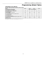
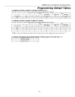
Programming Default Tables  

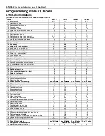
LYNXR-2 Control Defaults 

(boldface indicates defaults that differ between tables)


Function 

Table 1 

Table 2 

Table 3 

Table 4 

*20 

Installer 

code 

4112 4112 4112 4112 

*21 

Quick 

arm 

enable 

1 1 1 1 

*22 

Keypad 

backlight 

timeout 

0 0 0 0 

*23 


Forced 

bypass 

0 0 0 0 

*24  RF house ID code 

0,0 

0,0 

0,0 

0,0 

*25  Powerline carrier device house code 

*26 

Chime-by-zone 

0 0 0 0 

*27 

Real-time 

clock 

display 


1 1 1 1 

*29  Daylight saving time start/end month 

3,11 

3,11 

3,11 

3,11 

*30  Daylight saving time start/end weekend  

2,1 

2,1 

2,1 

2, 1 

*31  Single alarm sounding per zone 

*32 

Sounder 

timeout 

0 0 0 0 

*33 

Alarm 

bell 

timeout 

1 1 1 1 

*34 

Exit 

delay 


7,0 6,0 7,0 7,0 

*35  Entry delay 1 (zone type 01) 

3,0 

4,5 

3,0 

3,0 

*36  Entry delay 2 (zone type 02) 

6,0 

6,0 

6,0 

6,0 

*37  Audible exit warning/quick exit 

1,1 

0,1 

1,1 

1,1 

*38  Confirmation of arming ding 

*39  Power up in previous state 

*40 

PABX 

access 

code 

--- --- --- --- 

*41 

Primary 

phone 

number 

--- --- --- --- 

*42 

Secondary 

phone 

number 

--- --- --- --- 

*43  Primary subscriber account number 

15,15,15,15 

15,15,15,15 

15,15,15,15 

15,15,15,15 

*44  Secondary subscriber account number 

--- 

--- 

--- 

--- 

*46  “Follow Me Reminder” Phone Number 

--- 

--- 

--- 

--- 

*47 

Phone 

system 

select 

5 5 5 5 

*48 

Report 

format 

7,7 7,7 7,7 7,7 

*49 

Split/dual 

reporting 

0 0 0 9 

*50  15 second dialer delay (burglary) 

*51  Periodic test report  

*52  First test report offset  

*53 


Sescoa/radionics 

select 

0 0 0 0 

*54   Lack of usage notification 

*55 

Reporting 

Channels 

0 0 0 0 

*56  Enhanced Zone programming 

See *56 table 

See *56 table 

See *56 table 

See *56 table 

*58 

RF 

jam 

detection 

0 0 0 0 

*59  Exit error report code 

*60 

Trouble 

report 

code 

1,0 1,0 1,0 1,0 

*61  Bypass report code  

0,0 

0,0 

0,0 

0,0 

*62  AC loss report code  

0,0 

0,0 

0,0 

0,0 

*63  Low battery Report code  

1,0 

1,0 

1,0 

1,0 

*64 

Test 

report 

code 

1,0 1,0 1,0 1,0 

*65 

Open 

report 

code 

0 0 0 0 

*66  Arm away/stay report code 

0,0 

0,0 

0,0 

0,0 

*67  RF transmitter low battery report code 

1,0 

1,0 

1,0 

1,0 

*68 

Cancel 

report 

code 

1,0 1,0 1,0 1,0 

*70 

Alarm 

restore 

codes 

1 1 1 1 

*71  Trouble restore report code 

1,0 

1,0 

1,0 

1,0 

*72  Bypass restore report code  

0,0 

0,0 

0,0 

0,0 

*73  AC restore report code  

0,0 

0,0 

0,0 

0,0 

*74  Low battery restore report code  

1,0 

1,0 

1,0 

1,0 

*75  RF transmitter low battery restore report code 

1,0 

1,0 

1,0 

1,0 

*76  Test restore report code 

0,0 

1,0 

0,0 

0,0 

*77  Dynamic Signaling Delay/ Dynamic Signaling Priority 

0,0 

0,0 

0,0 

0,0 

*78  Programmable Tone Generation Time 

0,0 

0,0 

0,0 

0,0 

*80  Powerline Carrier Devices 

See *80 table 

See *80 table 

--- 

See *80 table 

*81  Zone lists for devices 

See *81 table 

See *81 table 

See *81 table 

See *81 table 

*84  Assign zone voice descriptors 


Refer to *84  Programming 


*86 

Multi-mode 

(E-mail 

notification) 

0 0 0 0 


Summary of Contents for LYNXR-2 Series Security System

Page 1: ...ity Systems Installation and Setup Guide ARMED READY BYPASS NO DELAY RECORD TEST FUNCTION STATUS VOLUME PLAY CODE LIGHTS ON LIGHTS OFF CHIME ESCAPE ADD DELETE SELECT OFF 1 2 3 6 AWAY 4 5 AUX STAY 0 7 8 9 K15011 7 08 Rev A ...

Page 2: ...the hallway outside may not wake up the sleeper if the door is closed Install a smoke detector inside bedrooms where electrical appliances such as portable heaters air conditioners or humidifiers are used Install a smoke detector at both ends of a hallway if the hallway is more than 40 feet 12 meters long Install smoke detectors in any room where an alarm control is located or in any room where al...

Page 3: ...U MODE 45 83 ENHANCED SEQUENTIAL MODE 47 84 ASSIGN ZONE VOICE DESCRIPTORS 50 85 RECORD CUSTOM VOICE DESCRIPTORS 52 REMOTE PROGRAMMING CONTROL DOWNLOADING 53 SYSTEM OPERATION 55 KEYPAD FUNCTION SUMMARY 60 TESTING THE SYSTEM 61 SYSTEM COMMUNICATION 62 TROUBLESHOOTING GUIDE 65 PROGRAMMING DEFAULT TABLES 68 LYNXR 2 CONTROL DEFAULTS 68 LYNXR 2SIA CONTROL DEFAULTS 70 REGULATORY AGENCY STATEMENTS 74 LIMI...

Page 4: ... 4 ...

Page 5: ...t for burglary panic Temporal pulse output for fire alarms Long range radio audio alarm verification PROGRAMMING Options stored in EEROM Can be uploaded downloaded or controlled via IBM compatible computer using Compass downloader software and specified HAYES modem or via capable GSM or IP communications module Voice prompt programming mode COMMUNICATION Ademco Low Speed Sescoa Radionics Ademco Ex...

Page 6: ...ough the appropriate openings in the back plate 5 After wiring connections are made carefully reconnect the ribbon cable to the front assembly PC board connector properly aligning the red wire 6 Snap the front assembly to the back plate so it is secured by the locking tabs LOCKING TABS RED WIRE MARKING DISCONNECT THIS END ONLY 09012 002 V0 LOCKING TABS LOCKING TABS Desktop Mounting For desktop use...

Page 7: ...ets only To test the integrity of the ground terminal use a three wire circuit tester with neon lamp indicators such as the UL Listed Ideal Model 61 035 or equivalent available at most electrical supply stores a Connect terminal 1 to a good earth ground 2 Make Phone Line Connections For local or full line seizure follow the appropriate steps below Local Seizure a Connect the incoming phone line to...

Page 8: ... is lost 3 Make External Sounder Connections The control panel supports either a 6 14VDC piezo sounder 30mA max or 6 14VDC bell 120mA max e g ADEMCO WAVE2EX a Connect a piezo sounder to terminals 10 and 11 OR a bell to terminals 11 and 12 4 Disable Local Sounder Option If required the Master Keypad s built in piezo sounder can be disabled a Remove the shorting jumper shunt on the terminal board 5 ...

Page 9: ...ce as follows refer to the Installation Instructions for device that you are installing for additional information The wire run between the LYNXR 2 Series and the Communications Device must not exceed ten 10 feet UL UL UL UL The 7845i ENT has been evaluated by UL for Household Burglary installations but has not been evaluated for Household Fire installations AlarmNet 7847i L Communications Device ...

Page 10: ...e DSL modem and router or to an Intranet LAN via the appropriate Ethernet connection if applicable UL UL UL UL AlarmNet 7845GSM and 7845i GSM modules have not been evaluated by UL When available 7845GSM 7845i GSM LYNX SUPER HIGH CAPACITY BATTERY OPTIONAL REQUIRED FOR 24 HR BACKUP 09012 018 V0 GND Z3 OR DATA OUT Z1 Z2 OR DATA IN ECP VOLTAGE INPUT RED BLK GRN YEL RED BLK GRN YEL 4 5 6 3 5 4 4 WIRE C...

Page 11: ...CATIONS CABLE 09012 017 V1 SCREW 3 AUDIO CABLE GSMVL ONLY ANTENNA GSML GSMVL Installing the GSML GSMVL Communications Module LRR IP Communications Device 24 Hour Standby Power If you are installing the AlarmNet 7845GSM 7845i GSM or 7847i L and require 24 hour standby you must install the Super High Capacity battery P N WALYNX RCHB SHA in the control The 7845i ENT and 7845i can not be used for inst...

Page 12: ...w battery message is displayed and a report is sent to the central station In addition the system will beep once every 45 seconds to audibly indicate a low battery condition press any key to stop the beeping AC Power and Rechargeable Backup Battery Connecting AC Power and backup battery 1 Connect wires from the K10145X10 K10145CN in Canada AC Transformer to terminals 15 and 16 as shown in the wiri...

Page 13: ...tainer and disconnect the battery pack connector from the receptacle on the terminal block PC board 3 Remove the battery pack from the back plate 4 If required replace the tape that secures the battery pack 5 Install a replacement battery pack P N LYNXRCHKIT SC LYNXRCHKIT HC or LYNXRCHKIT SHA into the back plate 6 Install the battery retainer 7 Connect the battery connector to the receptacle on th...

Page 14: ...for some transmitters keypads that may be carried off premises 5804 5804BD 5804BDV and 5804E each transmitter is supervised by a check in signal that is sent to the receiver at 70 90 minute intervals If at least one check in is not received from each supervised transmitter within a 12 hour period the missing transmitter number s and FAULT will be displayed The supervision for a particular transmit...

Page 15: ... keypads that have a two second delay on the special function keys or two button panic pairs built in keypad s two button panic pairs Go No Go Test Mode 5804E encrypted High Security devices must be activated while the system is in Go No Go Test Mode Refer to the transmitter s installation instructions for complete details The system will confirm enrollment of the encrypted device by beeping two t...

Page 16: ...819 ENROLL AS RF LOOP 2 REED LOOP 3 TERMINALS LOOP 1 TERMINALS 5800WAVE PROGRAM HOUSE ID 5800Micra ENROLL AS RF 5800CO ENROLL AS RF 5801 ENROLL AS UR OR RF 5800SS1 ENROLL AS RF 5800RL SET HOUSE ID LOOP 3 LOOP 1 LOOP 2 LOOP 4 YOU MUST ENROLL THIS BUTTON 5849 ENROLL AS RF 5894PI ENROLL AS RF LOOP 1 SOUND 5802MN2 ENROLL AS UR OR RF LOOP 1 LOOP 1 5878 ENROLL AS BR 5853 ENROLL AS RF 5850 GBD ENROLL AS ...

Page 17: ...ethods to enter Programming Mode 1 Press both the and keys at the same time within 50 seconds after power is applied to the Control or from exiting Programming mode OR 2 After power up enter the Installer Code 4112 800 to enter Expert Programming mode This method disabled if Program mode is exited using 98 OR enter Installer Code 4112 888 to enter Voice Prompt Programming mode If a different Insta...

Page 18: ...ad Loading Factory Defaults 97 To load the factory defaults enter 97 then press number 1 2 3 or 4 to select from default tables 1 4 or press 0 if you are not selecting a default table Refer to the Programming Default Tables section of this manual to view the tables If a default table is loaded any data that has already been programmed into the system will be changed according to the default table ...

Page 19: ...rovides an instant alarm if the entry exit zone is not violated first and protects an area in the event an intruder has hidden on the premises before the system is armed or gains access to the premises through an unprotected area Zone Characteristics Delayed alarm using the programmed entry exit time if entry exit types 01 or 02 or interior with delay type 10 zone is faulted first Instant alarm in...

Page 20: ... any other fire zone is faulted during the 30 second delay window a fire alarm is immediately provided for that zone An alarm for original fire zone will also be provided if that zone is still faulted afterward If there are no fire alarms after the 30 second delay expires the system will open a 60 second window If any fire zone is faulted during that window a fire alarm will immediately be provide...

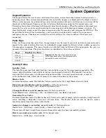
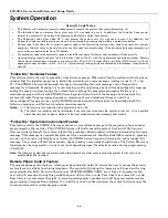
Page 21: ...e remains unchanged 21 Quick Arm Enable 0 do not allow quick arm 1 allow quick arm If enabled security code is not required to arm the system The user simply presses and holds down the AWAY or STAY key to arm 22 Keypad Backlight Timeout 0 no timeout always backlight keys 1 turn backlighting off after inactivity This option allows the choice of either always backlighting the keypad or turning the b...

Page 22: ...ause 3 pulses pause 3 pulses Temporal pulse sounding for a CO alarm consists of the following 4 pulses pause 4 pulses pause 4 pulses pause 33 Alarm Bell Timeout 0 No timeout 1 4 minutes 2 8 minutes 3 12 minutes 4 16 minutes This field determines whether the external sounder will shut off after time allowed or continue until manually turned off UL installations must be set for a minimum of 4 min op...

Page 23: ...ble Exit Warning Quick Exit Exit Warning Quick Exit 0 no exit warning sound 0 no quick exit 1 provide exit warning sound when armed AWAY 1 allow quick exit Exit Warning Sound consists of slow continuous beeps until last 5 seconds when it changes to fast beeps The warning sound will end at the termination of exit delay Quick Exit If enabled user can restart the exit delay time after arming in STAY ...

Page 24: ...nd cross zone can go into alarm immediately even after the cross zone time This is to detect scenarios involving multiple break ins of a premises UL This option is not for use in UL installations DIALER PROGRAMMING 40 50 Fields 40 41 42 Enter up to the number of digits shown Enter 0 9 11 for 12 for 13 for a pause 2 seconds Field 40 is used to program different features in the LYNXR 2 and LYNXR 2SI...

Page 25: ...44 See blank Programming Form for examples of account number entries If using the paging feature do not enter a leading 0 in the subscriber account number and do not use digits A F anywhere in the number Some paging systems provide voice mail capability which is activated by a leading 0 in the message Enter digits 0 9 11 B 12 C 13 D 14 E or 15 F 43 Primary Subscriber Account No Enter a four or ten...

Page 26: ...able call waiting Note If using pulse dialing you must enter the numbers slowly in order to allow the pulse dialer time to operate LYNXR 2SIA ONLY Call waiting warning tones can interfere with Central stations reporting The Call Waiting Cancel option should be selected if the reporting phone line has call waiting service The Call Waiting Cancel command must also be programmed in Field 40 If the Ca...

Page 27: ...e System Report Format Options 10 13 send reports to the primary phone number in a format defined in Field 48 and sends voice message to the secondary phone number entered in Field 42 The message is a repeatable system status announcement If the manual paging option has been programmed in Field 87 the message will repeat system system The message can be terminated by pressing any key on the teleph...

Page 28: ...ger features are selected AAV will not be available even if enabled in 91 UNLESS option 5 is selected in 55 Radio only If option 5 is selected in 55 AAV will be established on the primary channel because Follow me System and Pager are not available on the radio s audio channel The following table shows the only valid combinations of communication channels and reporting options It is the responsibi...

Page 29: ... burglary cannot be cancelled Auto Stay Arming If this feature is enabled and the control panel has been armed Armed Away at the LYNX keypad or RF keypad the system will switch to the Armed Stay mode if the Exit Time has expired and no exit has been made Exit Time Restart Exit Delay Restart Reset This option allows the systems to restart the exit delay time after arming in STAY mode by entering th...

Page 30: ... Alarm condition will also result if a fault occurs in an exit or interior zone within 2 minutes following the end of the exit delay and an Exit Alarm message will be sent to the central station If Contact ID format has been programmed the message will contain the zone number and error code 374 Trouble Exit Error If 4 2 format is used the digit entered in this field will be sent followed by the se...

Page 31: ...ot valid the control will emit a single long beep indicating that the selection has been rejected The control replaces the selection with the default value 10 which is displayed on the keypad and advances to the next field Field 69 Field 69 only applies to the LYNXR 2SIA control 69 Recent Closing Report LYNXR 2SIA ONLY This feature is always enabled A report code can be entered if formats other th...

Page 32: ...nction The Dynamic signaling options are shown as follows Reporting Option Enable Disable Device Field 55 Dynamic Signaling Delay Dynamic Signaling Field 77 Primary Phone only Report is sent to Primary phone with No Dynamic Signaling Delay 0 Telco Line only no Radio 1st Entry enter a delay for the first entry 2nd Entry 0 Primary phone only LRR IP only Report sent to communications device with No D...

Page 33: ...s installed in the control Otherwise enter 00 to disable 86 Multi mode E mail notification 0 Disable multimode devices 1 Enable multimode device address 6 only 2 Enable multimode device address 7 only 3 Enable multimode addresses 6 7 Enable if using AlarmNet Remote Services e mail notification multi mode feature The address es used must also be enabled in the AlarmNet communication device For more...

Page 34: ... in field 49 AAV cannot be used 6 If AAV is selected and LRR IP communications device is enabled you must enter 0 primary dialer preferred channel as the second entry in Field 77 Field 92 Field 92 is used to program different features in the LYNXR 2 and LYNXR 2SIA controls Please be sure that you use the correct field for the control being installed 92 Number of Reports In Armed Period Note This f...

Page 35: ...tection Count For Downloading Remote Phone Control 0 disable station initiated download and remote phone 1 14 number of rings before control picks up phone line 15 defeat answering machine Enter 15 to select defeat answering machine mode If an answering machine is on the premises you need to dial the premises and hang up on the first ring Wait at least five 5 seconds but no more than 22 seconds an...

Page 36: ... enter Zone Programming Menu Mode You must refer to these instructions or to the Program Form while programming the system because the keypad display does not show prompt titles Instead prompts are indicated by a number letter combination The prompts for 56 are as follows A 02 Zone Number for entering the zone number b Zone Type for entering zone type C Report Code for entering the zone s report c...

Page 37: ...ry Exit 1 10 Interior w Delay 02 Entry Exit 2 14 Carbon Monoxide 03 Perimeter 16 Fire with verification 04 Interior Follower 20 Arm Stay 05 Trouble Day Alarm Night 21 Arm Away 06 24 Hr Silent 22 Disarm 07 24 Hr Audible 23 No Alarm Response 08 24 Hr Aux 24 Silent Burglary Notes 1 ZT16 is only available on the LYNXR 2SIA version 2 ZT16 is not for use with manually actuated devices including fire key...

Page 38: ...r all other device types four 4 transmissions are required fault restore and fault restore A single beep will sound after the second transmission confirming that the loop and serial number have been captured Following the fourth transmission the system will confirm that the loop number and serial number have been learned and announce the Voice Descriptor for the zone if it is programmed followed b...

Page 39: ...al number prompt 1b Copy the previous serial number Enter 2 to copy the previous serial number entered Return to Prompt E Enter to return to Loop Number prompt E Enter transmitter later Enter 0 or if you wish to enter the transmitter later using the 83 Enhanced Sequential Mode described later in this manual Notes 1 The panel will listen only when it is in the idle loop waiting for key entry and a ...

Page 40: ...tor 3 descriptor 3 will be announced 8 accept word and advance to next zone prompt A entire zone descriptor will be announced Press any other key to repeat the selected word see 84 Assign Zone Voice Descriptors section for vocabulary index Use the 6 or 8 key to advance as described To change the entered index number before pressing 6 or 8 simply press desired 2 digit vocabulary index number If des...

Page 41: ...by Event An event is the condition alarm fault trouble that must occur to a zone or group of zones zone list in order to activate the device These conditions apply only when a zone list is used The different choices for EVENT are listed below and in the Programming Powerline Carrier Devices paragraph that follows ALARM Device activates upon any alarm in an assigned zone in the zone list FAULT Devi...

Page 42: ...ce to de activate During normal system operation any devices may be manually started by keypad entry of Code 4 n or manually stopped by keypad entry of Code 7 n where n the device number to be controlled Code is required for devices 7 and 8 For devices 1 6 code is not required See User Manual for more information Programming Powerline Carrier Devices While in Program mode press 80 to enter Device ...

Page 43: ...Pulse on off 1 sec ON 1 sec OFF continue return to previous prompt Enter the 1 digit action 0 3 for the device being programmed current action is displayed Notes 1 If 3 is entered pulse only up to 3 different devices can be pulsed if one of the devices is a siren horn X10 Powerhouse Security model SH10A In addition the siren horn cannot be manually activated using the lights on lights off keypad c...

Page 44: ...larm 31 End of Exit Time 40 Bypassing 32 Start of Entry Time 42 System Battery Low 33 Any Alarm except ZT 08 09 14 or 16 43 Communications Failure 36 At Bell Timeout 58 Duress Or at Disarming which ever occurs earlier SIA ZT 16 must be used in SIA fire applications F zl Stop Zone List 1 3 zone list to stop this device action 0 zone list not used continue return to previous prompt If a zone list wi...

Page 45: ...ble entries The right most column provides a further explanation of the entries Notes 1 Any list may include any or all of the systems zone numbers 2 A zone list can be assigned to more than one Powerline Carrier Device 3 Entering a number other than one specified will give unpredictable results 4 Do not assign zones with zone types 20 21 or 22 to a zone list 5 LYNXR SIA ONLY Zone List 2 should be...

Page 46: ...nue to next prompt 1 delete the current zone list Enter 1 to delete the zone list All zones in the zone list will be deleted automatically and programming will return to the ZONE LIST NUMBER prompt Enter 0 to save the zone list or delete specific zones from the list d Delete Zones from List 1 continue to delete zones prompt 0 don t delete continue to next zone list number prompt A 01 return to zon...

Page 47: ...ber into four zones Note Use this mode only after all other zone information has been programmed including transmitter loop numbers except for button type zones over zone number 26 The panel will stop at zones 26 30 34 and 38 and zone data can be entered as a default here While in Program mode press 83 to enter Enhanced Sequential Mode The prompts for 83 are as follows A 02 Zone Number for enterin...

Page 48: ...eviously entered you may enter the enroll serial number mode 1A by entering 1 Enter 2 to copy the last serial number that was entered A serial number must be entered in order to be copied If no serial is stored in the buffer and a copy is attempted the panel will emit a long beep indicating an invalid operation If the transmitter s serial number has been previously entered you may view the present...

Page 49: ...nce the Voice Descriptor if it is programmed followed by three beeps and return to Prompt 1A and LC will be displayed No additional transmissions are needed for confirmation Manual Entry Enter the 7 digit serial number printed on the transmitter If you enter an incorrect digit press the key to backup to prompt 1A and start over When all 7 digits are entered press the key If less than 7 digits are ...

Page 50: ...ed b vv Descriptor 1 Enter 2 digit vocabulary index number of first descriptor word for this zone 6 accept word and advance to descriptor 2 descriptor 2 will be announced 8 accept word and advance to prompt A for next zone Press any other key to repeat the selected word Enter 2 digit vocabulary index number of first descriptor word for this zone 6 accept word and advance to descriptor 2 descriptor...

Page 51: ...BRARY 13 LIVING 53 LIVING ROOM M 14 MAIN 15 MASTER 54 MASTER BEDROOM 55 MEDICAL 84 MESSAGE 56 MOTION DETECTOR N 57 NINE 16 NORTH 58 NURSERY O 59 OFFICE 60 ONE 17 OUTSIDE P 61 PATIO 62 POLICE 18 POOL R 63 REAR 19 ROOM S 64 SECOND FLOOR 65 SEVEN 20 SHED 21 SHOP 66 SIDE 67 SILENT POLICE 68 SIX 69 SLIDING 22 SMOKE 23 SOUTH 24 STORAGE 85 SYSTEM T 25 THIRD FLOOR 75 THREE 76 TRANSMITTER 77 TWO U 78 UPSTA...

Page 52: ...de upon which this prompt blinks indicating the mode is inactive A 7d Custom Descriptor Number 0 exit mode 1 enter mode Enter 7 d Note d 0 4 each representing custom word 70 71 72 73 or 74 respectively Any existing word will be announced Press to start recorder Begin speaking immediately after the third beep Speak the desired word clearly near the microphone Recording stops after 1 5 seconds 6 acc...

Page 53: ...rmation Equipment required to download to a system at the premises An IBM PC compatible computer and appropriate interconnecting cables Either a HAYES brand SMARTMODEM 1200 Level 1 2 or higher external or Level 1 1 or higher with 4 position DIP switch internal style a HAYES brand Optima 336 external a HAYES brand Optima 24 Plus FAX96 or an Ademco CIA Modem or via a capable GSM or IP communications...

Page 54: ...keypad will become inactive and will display CC 2 The keypad will become active after the download communication is terminated 3 The detailed operation of the download functions is covered in the installation instructions for the Compass Downloader for Windows Remote Programming Advisory Notes Keypad entries are ignored during the time interval stated above A copy of the program downloaded may be ...

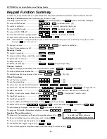
Page 55: ...time The panic functions are identified by the system as follows Keys Displayed as Zone 1 95 99 3 96 Important For the silent panic functions to be of practical value the system must be connected to a central station Security Codes Installer Code The installer programs the 4 digit Installer Code initially as part of the programming procedure The factory default Installer Code is 4 1 1 2 but may be...

Page 56: ...ill redial the programmed number a maximum of seven additional times or until it is acknowledged Pressing any key on the LYNXR 2 Series keypad will terminate acknowledge both the follow me reminder and the local reminder announcements Notes 1 This feature is only supported if programmed in field 49 2 The follow me reminder will be terminated if any other event requires the system to dial out or if...

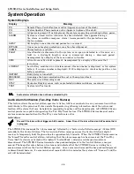
Page 57: ... 4 Device activates starts that device Security Code 7 Device de activates stops that device Code is required for devices 7 and 8 Code is not required for devices 1 6 Exit Error Alarm Displays The system will display the following if programmed in Field 59 Display Meaning CA will appear along with a zone indication if an exit or interior zone contained a fault during closing at the time the exit d...

Page 58: ...o alarm verification has not been evaluated by UL Audio Alarm Verification Two Way Voice Feature This feature allows the central station operator to listen talk to or conduct a two way conversation with an individual s at the premises It also assists the operator in gathering information about the nature and location of the alarm that may be helpful in responding to police and fire departments All...

Page 59: ... Note When entering AAV commands make sure the Central Station receiver has been disconnected from the phone line otherwise AAV commands may not go through Key Function 1 Talk Mode Pressing the 1 key on the touch tone phone enables one way voice communication from the central station to the violated premises and allows the operator to talk communicate through the LYNXR 2 Series speaker In this mod...

Page 60: ...age replay Volume Control To adjust message playback system announcement volume FUNCTION VOLUME 3 or 6 To mute system announcements FUNCTION VOLUME OFF To restore unmute announcement volume FUNCTION VOLUME 3 or 6 Other Functions To set the time and date FUNCTION 63 To set the scheduling FUNCTION 64 To activate or deactivate X10 devices 1 6 FUNCTION LIGHTS ON or LIGHTS OFF 2 digit device no To acti...

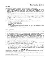
Page 61: ...ts will be in progress 1 Arm the system and fault one or more zones After 15 seconds if optional dialer delay is selected silence alarm sounder s by entering the code and pressing OFF Check entry exit delay zones 2 Check the keypad initiated alarms that are in the system by pressing the Panic key pairs If the system has been programmed for audible emergency the keypad will emit a steady alarm soun...

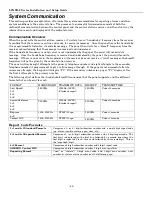
Page 62: ... and eight attempts to the secondary telephone number if programmed to get a valid message through If the panel is not successful after its numerous attempts the keypad will display FC If the secondary number is a pager FC displays after the first 8 attempts to the primary number The following chart defines the handshake kissoff frequencies that the panel supports and the different formats that ca...

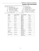
Page 63: ... Code 1st 2nd digits O Open Code 1st Digit RLLB Battery Restore Code 1st 2nd digits Zone numbers for 99 1 95 3 96 Duress 92 Report 3 1 4 1 Standard 3 1 4 1 Expanded 4 2 Alarm SSS S A SSS S A AAA A Z SSSS AZ Trouble SSS S T SSS S T TTT T t SSSS Tt Bypass SSS S B SSS S B BBB B b SSSS Bb AC Loss SSS S E SSS S E EEE E AC SSSS EAC Low Battery SSS S L SSS S L LLL L LB SSSS LLB Open SSS S O SSS S O OOO O...

Page 64: ...301 AC Power 302 Low System Battery Battery Test Fail 344 RF Jam Detected 353 ECP Communication Supervision failure case tamper or low battery 373 Fire Loop Trouble 374 Exit Error Alarm 380 Global Trouble Trouble Day Night Code Definition 381 RF Supervision Trouble 383 RF Sensor Tamper Trouble 384 RF Sensor Low Battery 401 Disarmed Armed AWAY NO DELAY Armed AWAY 403 Scheduled Auto Arm 406 Cancel b...

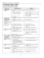
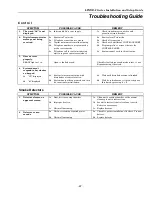
Page 65: ...M IP module communication failure displayed on RF Keypad only CA appears if an exit or interior zone contained a fault during closing at the time the Exit Delay ended e g exit door left open but the system was disarmed during the Entry Delay time The alarm sounder and keypad sound continuously but stop when the system is disarmed No message will be transmitted to the central station CC Modem Comm ...

Page 66: ...m keypad 4a System is in Test mode 4b A transmitter low battery has occurred and is displayed 4c A supervision fault has occurred 4d System low battery 4a Enter Code OFF to exit Test mode 4b Enter Code OFF and replace the battery 4c Check the transmitter indicated Restore communication to the receiver to cancel the condition 4d Replace system battery 5 There is no response to a transmitter in norm...

Page 67: ...DY light not on Open or faulted zone s Check for faulted zones and make intact or use Bypass arming if desired 4 System doesn t respond to keystrokes on keypad 4a CC displayed 4b dI displayed 4a System is in communication with downloader at central station 4b System has just been powered and is in its one minute initialization 4a Wait until download session is finished 4b Wait for initialization t...

Page 68: ...ual reporting 0 0 0 9 50 15 second dialer delay burglary 0 1 0 0 51 Periodic test report 0 3 0 0 52 First test report offset 2 2 2 2 53 Sescoa radionics select 0 0 0 0 54 Lack of usage notification 0 0 0 0 55 Reporting Channels 0 0 0 0 56 Enhanced Zone programming See 56 table See 56 table See 56 table See 56 table 58 RF jam detection 0 0 0 0 59 Exit error report code 1 0 1 1 60 Trouble report cod...

Page 69: ...r characters 89 Event log 80 full report code 0 0 0 0 0 0 0 0 90 Event logging 3 15 3 3 91 Alarm audio verification remote phone control 2 2 2 2 92 Number of reports in armed period 0 0 0 0 93 Flexible call back 0 0 0 0 94 Download phone number 95 Ring detect count for downloading remote phone control 15 15 15 15 Default Master Code 1 2 3 4 1 2 3 4 1 2 3 4 1 2 3 4 Default Duress Code By activating...

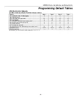
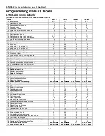
Page 70: ...mary secondary 7 7 7 7 7 7 7 7 49 Split dual reporting 0 0 0 9 50 Burglary abort window 2 2 2 2 51 Periodic test report 0 3 0 0 52 First test report offset 2 2 2 2 53 Sescoa radionics select 0 0 0 0 54 Lack of usage notification 0 0 0 0 55 Reporting channels 0 0 0 0 56 Enhanced zone programming See 56 table See 56 table See 56 table See 56 table 57 False alarm options 7 7 7 7 58 RF jam detection 0...

Page 71: ...0 0 0 87 Auxiliary Function 1 button paging 0 1 0 1 88 Pager characters 89 Event log 80 full report code 0 0 0 0 0 0 0 0 90 Event logging 3 15 3 3 91 Alarm audio verification remote phone control 2 2 2 2 92 Swinger shutdown 1 1 1 1 93 Flexible call back 0 0 0 0 94 Download phone number 95 Ring detect count for downloading remote phone control 15 15 15 15 Default Master Code 1 2 3 4 1 2 3 4 1 2 3 4...

Page 72: ...F 2 48 04 GARAGE DOOR 5 04 1 0 3 RF 1 56 MOTION DETECTOR 6 09 1 0 3 RF 1 22 02 SMOKE DETECTOR 26 21 1 0 5 BR 3 27 22 1 0 5 BR 2 28 20 1 0 5 BR 4 29 23 0 0 5 BR 1 30 21 1 0 5 BR 3 31 22 1 0 5 BR 2 32 20 1 0 5 BR 4 33 23 0 0 5 BR 1 92 1 0 95 08 1 0 96 09 1 0 99 07 1 0 NOTE Zone 2 to 41 are RF zones Zone 92 is Duress Zones 95 96 and 99 are keypad panics 56 ZONE ASSIGNMENT ALARM REPORT CODES FOR TABLE...

Page 73: ...6 2 33 36 80 DEFAULT TABLE APPLIES TO DEFAULT TABLE 4 devices 02 07 have no default values devices 10 15 have all default values set to 00 Start Stop Device Number Action Event Zone List Zone Type System Operation Restore of Zone List Zone type System operation 01 2 2 1 2 08 2 33 36 09 2 2 1 2 16 2 33 36 NOTE If using an X10 Powerhouse Security SH10A siren as device 08 you must change the device a...

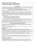
Page 74: ...er s Manual Unauthorized changes or modifications could void the user s authority to operate the equipment Federal Communications Commission FCC Part 68 This equipment complies with Part 68 of the FCC rules On the front cover of this equipment is a label that contains the FCC registration number and Ringer Equivalence Number REN You must provide this information to the telephone company when reque...

Page 75: ...red by those beams They cannot detect motion or intrusion that takes place behind walls ceilings floors closed doors glass partitions glass doors or windows Mechanical tampering masking painting or spraying of any material on the mirrors windows or any part of the optical system can reduce their detection ability Passive Infrared Detectors sense changes in temperature however as the ambient temper...

Page 76: ...out standard line security or encrypted line security or c 120 seconds for a system that does not transmit an alarm signal to a remote monitoring location SIA Quick Reference Guide 1 31 Single Alarm Sounding per Zone If 0 selected alarm sounding per zone will be the same as the number of reports in armed period set in field 92 1 if 1 report 2 if 2 reports 2 34 Exit Delay Options include 45 96 and ...

Page 77: ...ct and the version level if known along with any documentation that came with the product Note your Honeywell customer number and or company name Having this information handy will make it easier for us to serve you quickly and effectively You may contact Technical Support via Toll Free Fax Please include your return fax number You will receive a reply within 24 hours Technical Support 1 800 645 7...

Page 78: ...LYNXR 2 Series Installation and Setup Guide 78 Notes ...

Page 79: ...LYNXR 2 Series Installation and Setup Guide 79 Notes ...

Page 80: ...LYNXR 2 Series Installation and Setup Guide 80 Notes ...

Page 81: ...LYNXR 2 Series Installation and Setup Guide 81 Notes ...

Page 82: ...LYNXR 2 Series Installation and Setup Guide 82 Notes ...

Page 83: ...3 69 71 Aux key 33 Away mode 60 B Babysitter code 55 Back plate 6 Backlighting 21 Backup battery 12 13 Backup reporting 25 Battery life 14 Bell 86 BR 14 37 Burglary zones 22 Busy standby 65 Button transmitters 14 15 Button type 37 Button zones 37 Bypass 58 Bypass report code 68 70 Bypass restore report code 68 70 C Callback number 34 Cancel report code 68 70 Canceled alarm 30 Change the master cod...

Page 84: ...report code 68 70 Operator commands 59 Optima 24 Pplus FAX96 modem 53 Other features 5 Other functions 56 P PABX access code 24 68 70 Pager 27 Pager characters 69 71 Pager function 57 Pager message 33 Pager report format 27 Paging feature 33 Panic keys 55 Perimeter burglary 19 Periodic test report 68 70 Phone system select 68 70 Piezo 86 Play back a message 60 Plug in transformer 12 41 42 59 68 70...

Page 85: ...tem features 5 System displays 58 System operation 41 42 55 73 System power 5 System words 51 T Technical support 77 Telco handoff 53 Temporal pulse 22 Test mode 60 61 66 67 Test report code 68 70 Test restore report code 68 70 Testing the system 61 Time and date 60 Transmitter loop numbers 16 Transmitter supervision 14 Transmitters 14 Trouble by day 19 Trouble conditions 65 Trouble report code 68...

Page 86: ...ax Bell 6 14VDC 120mA max e g ADEMCO s WAVE2EX 3 Communication FORMATS SUPPORTED ADEMCO Express 10 characters sec DTMF TouchTone Data Tones 1400 2300Hz ACK 1400Hz KISSOFF ADEMCO Contact ID Reporting 10 characters sec DTMF TouchTone Data Tones 1400 2300Hz ACK 1400Hz KISSOFF ADEMCO Low Speed 10 pulses sec 1900Hz Data Tone 1400Hz ACK KISSOFF Radionics SESCOA 20 pulses sec 1800Hz Data Tone 2300Hz ACK ...

Page 87: ...E EVERY FOUR YEARS P N LYNXRCHKIT SC P N LYNXRCHKIT HC P N LYNXRCHKIT SHA RING TIP RING TIP DATA OUT SYNC IN POWERLINE CARRIER DEVICES GND DATA IN DATA OUT INCOMING PHONE LINE TO HANDSET PHONE LINE WARNING TO PREVENT RISK OF SHOCK DISCONNECT TELEPHONE LINE AT TELECOM JACK BEFORE SERVICING THIS UNIT ALL OUTPUT CIRCUITS ARE POWER LIMITED 1 2 3 4 8 6 5 11 7 10 12 15 16 13 14 PHONE FUTURE USE SOUNDERS...

Page 88: ...rranty information please go to www honeywell com security hsc resources wa 2 Corporate Center Drive Suite 100 P O Box 9040 Melville NY 11747 Copyright 2008 Honeywell International Inc www honeywell com security ÊK15011sŠ K15011 7 08 Rev A ...

Reviews: