background image

LYRIC INSTALLATION

33-00069EFS—01

2

CAUTION

Electrical Hazard.

Can cause electrical shock or equipment damage.

Disconnect power before beginning installation.

Mount Wall Cover

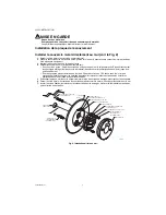
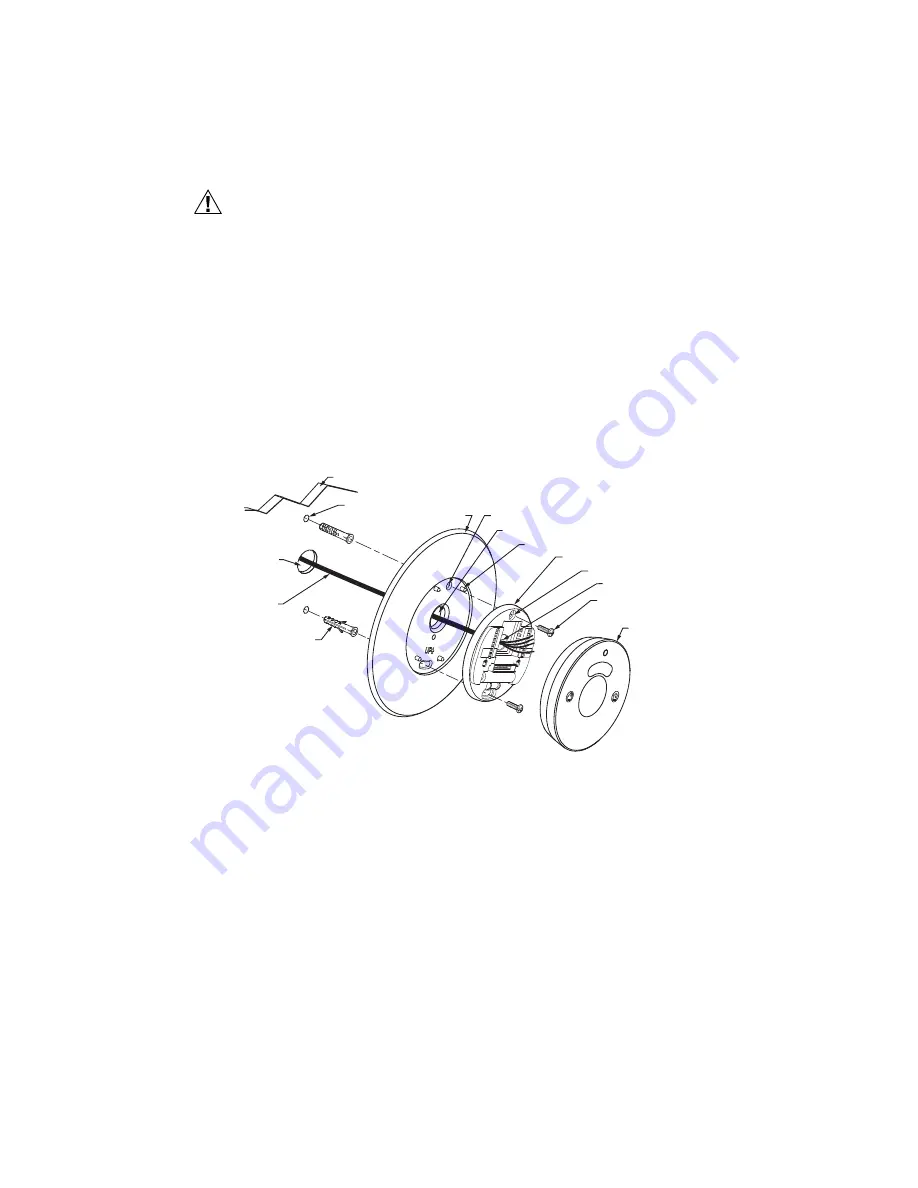
Mount Wall Cover Directly to Wall (See Fig. 2)

1.

Pull the wires through the wire hole on the wall cover.

2.

Position the wall cover on the wall with the arrow pointing up. Check that the wall cover is leveled (for appearance 

only).

3.

Use a pencil to mark the mounting holes.

4.

Remove the wall cover from the wall and proceed as follow:

• For drywall: Drill two 3/16-in. holes in the wall as marked. Tap the wall anchors (provided with the thermostat) 

into the holes, until the anchor collar touches the wall.

• For harder surface such as plaster: Drill two 7/32-in. holes in the wall as marked. Tap the wall anchors 

(provided with the thermostat) into the holes, until the anchor collar touches the wall.

5.

Position the wall plate on the wall cover using the 4 mounting posts and snap them together.

6.

Pull the wires through the wire hole on the wall cover / wall plate assembly. Position the assembly on the wall 

anchors.

7.

Insert the mounting screws (provided with the thermostat) into the wall anchors. Check leveling, if desired, and 

tighten the mounting screws.

Fig. 2. Mount wall cover, wall plate and thermostat directly to wall.

MOUNTING SCREWS (2)

(PROVIDED WITH 

THERMOSTAT) 

M35407

G

RC

Ya

Y

R

WIRE HOLE

WALL COVER

MOUNTING HOLES (2)

THERMOSTAT

WIRE HOLE

WALL PLATE

MOUNTING HOLES (2)

WALL

OPENING

WALL ANCHORS (2)

(PROVIDED WITH 

THERMOSTAT)

DRILLED

HOLES (2)

WALL

WIRE

AUX

O/B

L

C

W

W2

U2

U1

1 Wire

2 Wire

Universal

  Hum

  Dehum

   Vent

K

R

R & RC

MOUNTING POSTS (4)

Summary of Contents for Lyric

Page 1: ... head screws See Fig 1 Fig 1 THP2400A1019 wall cover assembly INSTALLATION When Installing this Product 1 Read these instructions carefully Failure to follow them could damage the product or cause a hazardous condition 2 Check ratings given in the instructions and on the product to make sure the product is suitable for your application 3 Installer must be a trained experienced service technician 4...

Page 2: ...laster Drill two 7 32 in holes in the wall as marked Tap the wall anchors provided with the thermostat into the holes until the anchor collar touches the wall 5 Position the wall plate on the wall cover using the 4 mounting posts and snap them together 6 Pull the wires through the wire hole on the wall cover wall plate assembly Position the assembly on the wall anchors 7 Insert the mounting screws...

Page 3: ...wires through the wire hole on the wall cover wall plate assembly Position the assembly on the bracket 4 Insert two 6 32 X 3 8 pan head screws Check leveling if desired and tighten the pan head screws Fig 3 Mount bracket wall cover wall plate and thermostat to a vertical 2 in X 4 in electrical box 6 32 X 5 8 FLAT HEAD SCREWS 2 BRACKET ELECTRICAL BOX 6 32 X 3 8 PAN HEAD SCREWS 2 M35408 G RC Ya Y R ...

Page 4: ...screws 2 Position the wall plate on the wall cover using the 4 mounting posts and snap them together 3 Pull the wires through the wire hole on the wall cover wall plate assembly Position the assembly on the bracket 4 Insert two 6 32 X 3 8 pan head screws Check leveling if desired and tighten the pan head screws Fig 4 Mount bracket wall cover wall plate and thermostat to a horizontal 2 in X 4 in el...

Page 5: ...e de plaques THP2400A1019 INSTALLATION Avant d installer ce produit 1 Lire attentivement les instructions Le fait de ne pas les suivre risque d endommager le produit ou de constituer un danger 2 Vérifier les caractéristiques nominales indiquées dans les instructions et sur le produit et s assurer que celui ci correspond bien à l application prévue 3 L installateur doit être un technicien d expérie...

Page 6: ...us dures telles que le plâtre Percer deux trous de 7 32 pouce dans le mur tel que marqués Enfoncer doucement les chevilles d ancrage fournies avec le thermostat dans les ouvertures pratiquées dans le mur jusqu à ce qu elles affleurent 5 Positionner la plaque murale sur le couvercle mural à l aide des 4 tiges de montage et enclenchez les ensemble 6 Passer les fils à travers l ouverture de l ensembl...

Page 7: ...avers l ouverture de l ensemble de plaque couvercle murale Placer l ensemble sur le support 4 Insérer deux vis 6 32 X 3 8 à tête cylindrique Vérifier la mise à niveau si nécessaire et serrer les vis Fig 3 Installation sur une boîte électrique de 2 po x 4 po en position verticale VIS 6 32 X 3 8 À TÊTE CYLINDRIQUE 2 G RC Ya Y R THERMOSTAT WIRE AUX O B L C W W2 U2 U1 1 Wire 2 Wire Universal Hum Dehum...

Page 8: ...vis 2 Positionner la plaque murale sur le couvercle mural à l aide des 4 tiges de montage et enclenchez les ensemble 3 Passer les fils à travers l ouverture de l ensemble de plaque couvercle murale Placer l ensemble sur le support 4 Insérer deux vis 6 32 X 3 8 à tête cylindrique Vérifier la mise à niveau si nécessaire et serrer les vis Fig 4 Installation sur une boîte électrique de 2 po x 4 po en ...

Page 9: ...Fig 1 Fig 1 Conjunto de la placa de pared THP2400A1019 INSTALACIÓN Cuando instale este producto 1 Lea detenidamente estas instrucciones De no seguirlas se podría dañar el producto o provocar una situación peligrosa 2 Verifique los valores nominales especificados en las instrucciones y en el producto para asegurarse de que el producto sea adecuado para su aplicación 3 El instalador debe ser un técn...

Page 10: ...e 7 32 in 5 6 mm en la pared donde los haya marcado Golpee ligeramente los tarugos que se proporcionan con el termostato en los agujeros hasta que los tarugos queden a ras con la pared 5 Coloque la placa de pared en la placa de cobertura utilizando los 4 puntos de montaje y fíjela a presión 6 Hale los cables a través del agujero para el cableado en el ensamble de la placa de pared placa de cobertu...

Page 11: ...e la placa de cobertura placa de pared Coloque el conjunto en el soporte 4 Inserte dos tornillos de cabeza troncocónica n 6 32 X 3 8 Verifique la nivelación si lo desea y apriete los tor nillos de cabeza troncocónica Fig 3 Monte el soporte la placa de cobertura la placa de pared y el termostato en un cajetín eléctrico vertical de 2 in x 4 in 5 1 cm x 10 2 cm BRACKET TORNILLOS DE CABEZA TRONCOCÓNIC...

Page 12: ...izando los 4 puntos de montaje y fíjelas entre ellas a presión 3 Hale los cables a través del agujero para el cableado en el ensamble de la placa de cobertura placa de pared Coloque el conjunto en el soporte 4 Inserte dos tornillos de cabeza troncocónica n 6 32 X 3 8 Verifique la nivelación si lo desea y apriete los tor nillos de cabeza troncocónica Fig 4 Monte el soporte la placa de cobertura la ...

Reviews: