background image

2


Installation


A

  Locating the Manning GM-1 

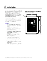
Figure 1: Mounting dimensions for the Manning GM-1 
Gas Monitoring Alarm System 

When unpacking the unit, inspect all boxes and 
contents for shipping damage. If any screws or 
other metal parts are missing, these must be found 
to ensure that the printed circuit boards will not be 
damaged when power is applied. 

6"

10 3/4"

5/16"

The control unit is designed to be mounted on a 
solid (non-vibrating) wall through four holes in the 
two mounting flanges. While the physical location 
must be determined in part by local conditions, it is 
important to consider the following: 

CAUTION


• 

Protect the Manning GM-1 from rain, snow, 
water sprays, cleaning crews, and physical 
damage. 

24 1/4"

Manning GM-1

Gas Monitor

Reset

Silence

• 

Mount the unit on a solid wall (non-
vibrating) at eye level for convenience in 
taking readings, servicing, etc. 

• 

The Manning GM-1 is 

NOT

 explosion proof. 

DO NOT MOUNT

 in a hazardous 

atmosphere. 

• 

Operating temperature for the Manning 
GM-1 is 0

o

 F to +120

o

 F. 

• 

Pre-punched holes are provided in the 
bottom of the enclosure for cable access. 

DO NOT

 drill holes in the top of the cabinet 

as this will void the warranty. 

• 

If hole drilling is required, be sure to remove 
all metal filings. 

• 

Mounting dimensions are included in Figure 1. 

Manning GM-1 Gas Monitoring Alarm System 19546 GM1 07/09 REVD  Copyright © 2009 Honeywell Analytics. All Rights Reserved. 7 

Summary of Contents for Manning GM-1

Page 1: ...idential Proprietary This work contains valuable confidential and proprietary information Disclosure use or reproduction outside of Honeywell Inc is prohibited except as authorized in writing This unpublished work is protected by the laws of the United States and other countries Instruction and Installation Manual Manning GM 1 Gas Monitoring Alarm System ...

Page 2: ...ent with and for its customers In no event is Honeywell liable to anyone for any indirect special or consequential damages The information and specifications in this document are subject to change without notice Manning is a registered trademark of Honeywell International Inc Other brand or product names are trademarks of their respective owners Honeywell Analytics 405 Barclay Blvd Lincolnshire IL...

Page 3: ...bol Definition ATTENTION Identifies information that requires special consideration CAUTION Indicates a potentially hazardous situation which if not avoided may result in minor or moderate injury It may also be used to alert against unsafe practices CAUTION symbol on the equipment refers the user to the product manual for additional information The symbol appears next to required information in th...

Page 4: ...outine maintenance procedures ATTENTION This manual must be carefully followed by all individuals who have or will have the responsibility for using or servicing the Manning GM 1 alarm system Warranties made by Honeywell Analytics with respect to this equipment will be voided if the equipment is not used and serviced in accordance with the instructions in this manual If in doubt about a procedure ...

Page 5: ...uring normal operation and a sensor fault monitoring circuit will indicate a fault and trip a dedicated fault relay if the signal falls below 1 4 mA The unit has an audible horn which will sound if an alarm or fault condition is detected The silence switch will silence the horn until the next event If an alarm condition initiates the horn the horn will clear automatically when the alarm relay clea...

Page 6: ...ut Fault Light and Relay always latch 10 second on delay Note All relays are normally energized and monitored by individual LEDs for ease of troubleshooting Relay Ratings 3 amps at 24 VDC or 120 VAC Form C providing NO normally open or NC normally closed option Enclosure 14 gauge steel gasketed 10 high x 8 wide x 4 deep NEMA 1 rated enclosure with plexiglass window Weight 11 lbs Operating Ambient ...

Page 7: ...the following CAUTION Protect the Manning GM 1 from rain snow water sprays cleaning crews and physical damage 24 1 4 Manning GM 1 Gas Monitor Reset Silence Mount the unit on a solid wall non vibrating at eye level for convenience in taking readings servicing etc The Manning GM 1 is NOT explosion proof DO NOT MOUNT in a hazardous atmosphere Operating temperature for the Manning GM 1 is 0o F to 120o...

Page 8: ...r manual for proper sensor cable See sensor manual for proper sensor location AC Power Wiring Never run AC circuits in the same conduit as the sensor cable Use only stranded cable for AC power relay outputs and sensor input cables Note Relays are energized in a non alarmed condition so that a power loss in the Manning GM 1 will result in an alarm The units must have a proper third wire ground for ...

Page 9: ...RELAY TP CURRENT DRAW ALARM RELAY FAULT RELAY SHLD GND 24 SIG FUSE RATING 250V 1 0 AMP White to SIG terminal of sensor Red to 24 terminal of sensor Black to GND terminal of sensor Bare wrap to SHLD terminal of sensor Relay rating 3 amp User must fuse to protect Note Green wire earth ground must be connected to grounding stud marked Risk of electrical shock Potential hazard Manning GM 1 Gas Monitor...

Page 10: ...ng GM 1 Gas Monitoring Alarm System 19546 GM1 07 09 REVD Copyright 2009 Honeywell Analytics All Rights Reserved 10 The Power LED indicates power to the monitoring unit This LED will flash during the one minute power up delay indicating that all relays are held in the normal condition to allow for sensor stabilization during power up The Fault LED indicates a signal input of less than 1 4 mA 0 14 v...

Page 11: ...tart up procedures and use radio contact Start Up Test One person exposes the sensor to a small amount of the gas that is being monitored The second person stays at the monitoring unit to determine that the sensor when exposed to the target gas is connected to the proper input responds and causes appropriate alarm functions F Troubleshooting The Fault Light and Fault Relay always latch when a faul...

Page 12: ...ive serial number and model number of unit Figure 4 Troubleshooting the Manning GM 1 Gas Monitoring Alarm System NO NC C NO NC C NO NC C L N WARNING RELAY 120 VAC WARNING RELAY WARNING ADJUST ALARM ADJUST TP WARNING TP ALARM TP SIG BOT TOP TP GND TP 20V MODEL G M MAINBOARD REV D C11 1 6 7 ALARM RELAY FAULT RELAY TP CURRENT DRAW ALARM RELAY FAULT RELAY SHLD GND 24 SIG FUSE RATING 250V 1 0 AMP 20V B...

Page 13: ...limited warranty does not cover consum able items such as batteries or items subject to wear or periodic replacement including lamps fuses valves vanes sensor elements cartridges or filter elements 3 Warranty Limitation and Exclusion Honeywell Analytics will have no further obligation under this limited warranty All warranty obligations of Honeywell Analytics are extinguishable if the Product has ...

Reviews: