Rev. C
7.15-10
HMXMU001018
10/06
7.15.10
I.R. Learn Mode
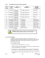
5. Press the remote control key for function 1 and release, LED 1 will momentarily be
steady and then flash again. To verify that the function has been correctly analyzed,
the RD490 module immediately regenerates the same function on the IR PPM (1)
output. The VCR device fitted to this output should respond. When you are happy
with the remote key analyzed, press the learn button again to store the last analyzed
IR remote control key. Note that LED 2 will now flash indicating that the function has
been stored and the RD490 is ready to learn function 2.
6. Repeat the process for each of the sixteen functions as listed in the function table.
LED’s 1-8 will progressively cycle as each function is learnt. The LED’s will cycle
twice. The first time the LEDs represent functions 1 to 8, while the second time
though represents functions 9 to 16.
7. To skip a function that is not required press the learn button. The RD490 will mark
that function as undefined and step on to the next one.
8. When all 8 functions have been addressed, all 8 LED’s will be flashing. Remove the
module from the subrack and select the DIP switches to one of the user-defined
modes (SW2). Replace the module back into the subrack and re-boot the system.
CAUTION:
If the IR remote control is moved away from
the IR sensor on the RD490 board while learning, a
GENERAL ERROR may be reported, terminating the learn
sequence. Be careful to hold the remote control
accurately near the IR sensor (35mm or 1.5”) and begin
the learn process again.
7.15.11 Workshop
Test
Mode
Workshop test modes are used to perform a complete hardware test of the RD490
module.
Hold-pressed LEARN-BUTTON during power-on RESET and hold for one (1) second. All
LED’s will flash for the usual 0.5 sec and then remain OFF until the LEARN-BUTTON is
released. The card will use its RS-232 comms. output to firstly identify the MODEL and
VERSION of the software installed. Test level (1) will begin immediately. To move on to
the next test level, press the LEARN-BUTTON again (hold for approx. 0.5 sec). A text
message is written via the RS-232 comms. output to indicate the TEST LEVEL that is
currently running.
TEST LEVEL (1)
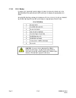
This is an individual and sequential LED test, cycling from the top LED to the bottom. It
also activates the PPM DRIVE outputs from output (1) to output (8).
Summary of Contents for MAXPRO-Net
Page 12: ...Rev C xii HMXMU01018 10 06 Notes ...
Page 20: ...Rev C xx HMXMU01018 10 06 Notes ...
Page 28: ...Rev C 4 2 HMXMU01018 10 06 Notes ...
Page 42: ...Rev C 7 2 HMXMU001018 10 06 Notes ...
Page 46: ...Rev C 7 2 4 HMXMU001018 10 06 Notes ...
Page 52: ...Rev C 7 3 6 HMXMU001018 10 06 Notes ...
Page 56: ...Rev C 7 4 4 HMXMU001018 10 06 Notes ...
Page 62: ...Rev C 7 6 4 HMXMU001018 10 06 Notes ...
Page 72: ...Rev C 7 9 6 HMXMU001018 10 06 Notes ...
Page 105: ...Rev C 7 11 17 HMXMU001018 10 06 ...
Page 106: ...Rev C 7 11 18 HMXMU001018 10 06 ...
Page 107: ...Rev C 7 11 19 HMXMU001018 10 06 ...
Page 108: ...Rev C 7 11 20 HMXMU001018 10 06 ...
Page 109: ...Rev C 7 11 21 HMXMU001018 10 06 ...
Page 110: ...Rev C 7 11 22 HMXMU001018 10 06 ...
Page 111: ...Rev C 7 11 23 HMXMU001018 10 06 ...
Page 112: ...Rev C 7 11 24 HMXMU001018 10 06 ...
Page 125: ...Rev C 7 12 13 HMXMU001018 10 06 ...
Page 126: ...Rev C 7 12 14 HMXMU001018 10 06 ...
Page 127: ...Rev C 7 12 15 HMXMU001018 10 06 ...
Page 128: ...Rev C 7 12 16 HMXMU001018 10 06 ...
Page 129: ...Rev C 7 12 17 HMXMU001018 10 06 ...
Page 130: ...Rev C 7 12 18 HMXMU001018 10 06 NOTES ...
Page 146: ...Rev C 7 15 12 HMXMU001018 10 06 Notes ...
Page 168: ...Rev C 7 19 2 HMXMU001018 10 06 HONEYWELL Copyright Honeywell Subject to change without notice ...
Page 170: ...Rev C 7 20 2 HMXMU001018 10 06 ...
Page 174: ...Rev C 8 4 HMXMU001018 10 06 8 3 PT321 CONNECTIONS ...
Page 175: ...Rev C 8 5 HMXMU001018 10 06 8 3 PT321 CONNECTIONS CONTINUED ...
Page 176: ...Rev C 8 6 HMXMU001018 10 06 8 4 PT323 CONNECTIONS ...
Page 177: ...Rev C 8 7 HMXMU001018 10 06 8 5 PT324 CONNECTIONS ...
Page 178: ...Rev C 8 8 HMXMU001018 10 06 8 6 PT325 CONNECTIONS ...
Page 179: ...Rev C 8 9 HMXMU001018 10 06 8 7 PT327 CONNECTIONS ...
Page 180: ...Rev C 8 10 HMXMU001018 10 06 8 8 RD390 LENS CONTROL EMULATOR CONNECTIONS ...
Page 181: ...Rev C 8 11 HMXMU001018 10 06 8 9 I O MODULE D25 CONNECTIONS ...
Page 182: ...Rev C 8 12 HMXMU001018 10 06 8 9 I O MODULE D25 CONNECTIONS CONTINUED ...
Page 198: ...Rev C 10 2 HMXMU001018 10 06 Notes ...


