background image


Rev. C 

8-7 

HMXMU001018 


10/06 

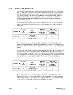
8.5 PT324 

CONNECTIONS 


Summary of Contents for MAXPRO-Net

Page 1: ...HMXMU001018 10 06 Rev C MAXPRO Net Crosspoint Matrix Video Switching System Hardware Installation Manual ...

Page 2: ...S A March 2005 Initial Release PCN 1980 B March 2006 Revised Installation Instructions C October 2006 Added detailed drawing for connecting to HVBMATPIT and VideoBloX Chassis in Chapter 12 Revised the part numbers for VideoBloX reference materials ...

Page 3: ...his equipment in a residential area is likely to cause harmful interference in which case the users will be required to correct the interference at their own expense CAUTION Changes or modifications not expressly approved by the party responsible for compliance could void the user s authority to operate the equipment This Class A digital apparatus complies with Canadian ICES 003 Cet appareil numér...

Page 4: ...n should be moved with care Quick stops excessive force and uneven surfaces may cause the product and cart combination to overturn 10 VENTILATION Slots and openings in the cabinet and the back or bottom are provided for ventilation and to ensure reliable operation of the equipment and to protect it from overheating These openings must not be blocked or covered The openings should never be blocked ...

Page 5: ...uire extensive work by a qualified technician to restore the unit to its normal operation e If the unit has been dropped or the enclosure has been damaged f When the unit exhibits a distinct change in performance this indicates a need for service 18 REPLACEMENT PARTS When replacement parts are required be sure the service technician has used replacement parts specified by the manufacturer or have ...

Page 6: ...e literature accompanying the product CAUTION CAUTION TO REDUCE THE RISK OF ELECTRIC SHOCK DO NOT REMOVE COVER OR BACK NO USER SERVICEABLE PARTS INSIDE REFER SERVICING TO QUALIFIED SERVICE PERSONNEL C A U T I O N RISK OF ELECTRIC SHOCK DO NOT OPEN WARNINGS WARNING TO REDUCE THE RISK OF FIRE OR ELECTRIC SHOCK DO NOT EXPOSE THIS PRODUCT TO RAIN OR MOISTURE WARNING DO NOT INSERT ANY METALLIC OBJECT T...

Page 7: ...NINGS CONTINUED WARNING OBSERVE PRECAUTIONS FOR HANDLING ELECTROSTATIC SENSITIVE DEVICES Grounded wrist straps must be worn and proper ESD safety precautions observed when handling the electrostatic sensitive printed circuit boards ...

Page 8: ...ERCHANTABILITY FITNESS FOR A PARTICULAR PURPOSE AND NONINFRINGEMENT ARE DISCLAIMED NO ORAL OR WRITTEN INFORMATION OR ADVICE GIVEN BY HONEYWELL ITS EMPLOYEES DISTRIBUTORS DEALERS OR AGENTS SHALL INCREASE THE SCOPE OF THE ABOVE WARRANTIES OR CREATE ANY NEW WARRANTIES SOME JURISDICTIONS DO NOT ALLOW THE EXCLUSION OF IMPLIED WARRANTIES SO THE ABOVE EXCLUSION MAY NOT APPLY TO YOU IN THAT EVENT ANY IMPL...

Page 9: ...emarks protects portions of MAX 1000 its software and its components Australian Patent 674652 693914 US Patent 5923364 5745166 British Patents GB2305061 B GB2323739 B GB2323740 B GB2323741 B Singaporean Patent 9700491 5 Australian Trademarks 679926 679927 679928 679929 679930 679931 US Trademark 75 142790 ...

Page 10: ...support department Call 972 620 6500 1 800 796 2288 in North America to register your software via telephone or contact tech support at MAXPRONETREGI HONEYWELL COM to register via email The form can be mailed to Honeywell s Technical Support Dept located at 12880 A Valley Branch Lane Farmers Branch TX 75234 Other information If you wish to minimize the requirement of technical support Honeywell pr...

Page 11: ...d be done immediately to activate you MAXPRO Net software What is the License key number You will need to know the licence number for the MAXPRO Net system you are ringing about The licence number is detailed at the top of this page as well as on the rear side of the SYSTEM floppy disk It can also be read from the title and registration page displayed within the system configuration editor program...

Page 12: ...Rev C xii HMXMU01018 10 06 Notes ...

Page 13: ...SHOOTING 5 1 5 1 GENERAL 5 1 5 2 EXAMPLE FAULT ANALYSIS 5 1 5 2 1 No Video from One Camera 5 1 5 2 2 No Video on One Monitor 5 2 5 2 3 No Text on Monitor or Monitors 5 2 5 2 4 No Operation from a Keyboard 5 2 5 2 5 Total System Failure 5 3 5 2 6 Problems with PTZ or Lens Operation 5 3 5 3 MACRO ERRORS 5 4 5 3 1 ERRORLOG Report in SetMax Configurator 5 6 5 4 DATA STREAM TESTING 5 7 5 4 1 RS232 Brea...

Page 14: ... 7 5 2 7 5 5 Indicators 7 5 2 7 6 RD105 105B SUBRACK CONTROLLER MODULE 7 6 1 7 7 RD200 TEXT INSERTION MODULE 7 7 1 7 8 MX205 TEXT INSERTION MODULE 7 8 1 7 9 RD315 PTZ SITE COMMUNICATIONS MODULE 7 9 1 7 9 1 PTZ Site Wiring 7 9 2 7 9 2 DIP Switch Setting 7 9 2 7 9 3 Setting Audio Communication Link Points 7 9 3 7 9 4 Direct RS 232 Control Or Data Testing 7 9 4 7 9 5 LED Indicators 7 9 4 7 9 6 Subrac...

Page 15: ...T RS 485 Bidirectional 7 10 16 7 11 RD378E PTZ SITE RECEIVER 7 11 1 7 11 1 Features 7 11 1 7 11 2 Power Supply 7 11 2 7 11 3 Communications 7 11 2 7 11 4 Motor Drive 7 11 5 7 11 5 Motor Time Out 7 11 8 7 11 6 Tamper Alarm Input 7 11 8 7 11 7 Installation Notes 7 11 8 7 11 8 Suitable cable sizing for PTZ heads when connecting to Site Receivers 7 11 8 7 11 9 RD378 PRIVACY ZONES 7 11 9 7 11 10 IO 378...

Page 16: ...2 7 15 3 7 15 6 DIP Switch Settings 7 15 3 7 15 7 Alarm Sense Setup SW1 4 way DIP switch 7 15 5 7 15 8 Error Display 7 15 7 7 15 9 Description of Control Functions 7 15 8 7 15 10 I R Learn Mode 7 15 9 7 15 11 Workshop Test Mode 7 15 10 7 16 RD494 RESISTIVE LADDER PERIPHERAL UNIVERSAL INTERFACE MODULE 7 16 1 7 16 1 General 7 16 1 7 16 2 Operation 7 16 1 7 16 3 Connector Details 7 16 3 7 16 4 Descri...

Page 17: ...CONNECTIONS 8 10 8 10 I O MODULE D25 CONNECTIONS 8 11 CHAPTER 9 SPECIALIST DOCUMENTATION 9 1 9 1 MAXPRO NET UPGRADE INSTALLATION FROM MAX 1000 9 1 9 1 1 Directions 9 1 9 2 RS 232 BASICS 9 2 9 3 VCR CONNECTIONS USING THE RD9022 9 3 9 3 1 Cable Manufacture 9 3 9 4 SINGLE SYSTEM JUNCTIONS SPLIT MATRICES 9 3 9 5 RECOMMENDED SIGNAL CABLES 9 5 9 5 1 Video cable 9 5 9 5 2 Audio telemetry cable 9 6 9 5 3 ...

Page 18: ... 8 11 13 INSTALLATION TIP 11 8 11 14 TECHNICAL NOTES 11 9 11 14 1 Hardware Mapping 11 9 11 14 2 Vertical Interval Switching 11 10 11 14 3 Black Pause Switching 11 10 11 14 4 PAL NTSC Determination 11 10 11 14 5 Cascading Multiple HMX32128 Subracks 11 11 11 15 HMX4248 I O MODULE FOR HMX32128 11 12 11 15 1 General 11 12 11 15 2 Installation 11 12 11 15 3 Contact Closure or End Of Line Modes 11 12 11...

Page 19: ...19 4 Operation 11 18 11 19 5 Installation Accessories 11 19 CHAPTER 12 VIDEOBLOX INTEGRATION WITH MAXPRO NET 12 1 12 1 CONNECTION DIAGRAMS 12 1 12 1 1 Connecting MAXPRO Net Server to Videoblox Chassis through HVBMATPIT 12 1 12 1 2 Connecting MAXPRO Net Server to Videoblox Chassis through VB Converter 12 2 12 1 3 Connecting MAXPRO Net Server to Videoblox Chassis through RS422 PCI Card 12 3 12 2 REF...

Page 20: ...Rev C xx HMXMU01018 10 06 Notes ...

Page 21: ...ical one step at a time identification of actions and operation By analyzing the LED indications and swapping suspect modules within the subrack it is possible to locate faults remotely with a Technician in front of the rack and an Engineer on the telephone For all of the following information it is assumed that service is being carried out on a previously operating system that is one that has bee...

Page 22: ...6 1 2 ACKNOWLEDGMENTS WINDOWS Registered trademark of the Microsoft Corporation SMARTEXT Trademark of Honeywell Inc FLASHBACK Trademark of Honeywell Inc MAXPRO and MAXPRO SYSTEMS LOGO are Registered Trademarks of Honeywell Inc ...

Page 23: ...taken not to handle electronic connection edges of circuit boards This is to minimize the chance of static damage and to avoid deposit of acids from the skin on critical surfaces d Do not poke your finger at components or touch IC pins These are all good ways of causing static damage Components are also physically delicate e All circuit modules equipped with memory components are to be protected f...

Page 24: ...rsonal contact with the chassis of the sub rack or computer before mating the connectors This will at least equalize static levels between the lead and the computer WARNING These procedures apply equally to both working and faulty circuit modules Careless handling storage and transporting will cause secondary or future faults ...

Page 25: ...ier to obtain a Return Authorization Number RAN This enables us to track your unit through our system Pack the units appropriately in the original packing if possible Honeywell will charge for repairs to equipment where damage has been caused by poor packing or transport Mark the Return Authorization Number RAN clearly on the outside of the box before shipping as well as in the accompanying docume...

Page 26: ...bers and any other details required on the purchase order Loan equipment is provided for fourteen days only Any extension to this time must be approved by Honeywell Failure to return equipment within fourteen days can affect future loan services and or credit facilities All loan equipment if not covered by warranty conditions is subject to a standard 20 re stocking fee All loan equipment must be r...

Page 27: ...isk Null modem cables and adapters IBM compatible computer with at least two serial ports Preferably a portable unit 4 2 ON SITE EQUIPMENT In most installations some form of communication is required from the camera to the control room monitors VHF or UHF hand held radios best suit this requirement Mobile telephones sometimes have application in this area Adjustments such as focus iris and camera ...

Page 28: ...Rev C 4 2 HMXMU01018 10 06 Notes ...

Page 29: ...er that with the macros the system features can be wide and varied First study the block schematic to understand the video paths the modules of concern and their slot locations A few hours spent on this at this point could save many hours of frustration Remember that each video module has a monitor point on the front of it for easy access of the test monitor Every module has at least one LED indic...

Page 30: ...tests 5 2 3 No Text on Monitor or Monitors Very similar to test as for the above Make a normal action and check that the data LEDs flash If text is lost on one monitor only then swap the module with another and reset If there is no text or no text update on any monitor and all the RD 200 modules are in one subrack then check that the data LED is flashing on the RD 105 module when selections are ma...

Page 31: ...t is very unlikely that components in a power supply will go faulty 5 2 6 Problems with PTZ or Lens Operation From operations on the keyboard it can be determined if a problem is partial at a site or a complete site fail A loss of communications at a site will cause the system alarm to activate for a PTZ fail In some instances a loss of video from the site may occur simultaneously This combined fa...

Page 32: ...ror 07 External alarm range error 08 Auxiliary control output range error 09 Invalid numeric evaluation error 10 Macro timer range error 11 Macro timer command error 12 Macro timer period error 13 System macro range error 14 Unknown video output channel 15 Unknown video input source 16 Invalid external alarm control logic 17 Invalid auxiliary output control logic 18 Invalid camera disable logic 19...

Page 33: ...nput 40 Invalid scan clear command 41 No dynamic macro timer available 42 User flag range error 0 Ù 8 only 43 Keyboard operator range error 0 Ù 100 only 44 User defined character range error in direct comm port writes 45 Undefined comm port number in direct comm port writes 46 Internal change network source 47 Internal change network source node command format error 48 Scan sequence entry number i...

Page 34: ...S104 301 050 27 NOV 96 17 39 50 MACRO ERROR 14 KB 34 KB34 TM001 113 114 The following table describes the two letter macro event code for the reported macro error Event Code Description of Event AS External alarm start macro AF External alarm finish macro VS Video input start macro VF Video input finish macro CB System cold boot macro WB System warm boot macro KI Keyboard key intercept macro key p...

Page 35: ...erver uses XON and XOFF signaling protocol and therefore does not require hardware handshake signals to be wired Only three 3 wires TX Data RX Data and Signal ground are required Using your RS232 test box even high speed data can be seen clearly as the LED indicators flash quickly This indicates that data is being generated but does not indicate its speed or other characteristics After connecting ...

Page 36: ...llows you to see any data corruption which can be very hard to find if you are not able to see the data Another very useful feature is the ability to insert a command in either direction PATCH232 has a recording mode that allows it to act as a data logger This feature is handy for any intermittent problems as you can leave PATCH232 to record all data passed over the link to be examined at a later ...

Page 37: ...r example you could send to the MAXPRO Net Control Computer the Subrack 1 reset command 1Z which would cause the MAXPRO Net software to WARM BOOT and update all subracks S Send command to SLAVE Pressing the S key enables you to enter a command that is sent to the SLAVE R Recorder log ON OFF Pressing the R key toggles the record status on and off When the record mode is enabled all data received is...

Page 38: ... be exercised from MaxMon MaxMon also provides recent system status Configuration status Monitor keyboard operator relations These run time diagnostics are particularly useful as they enable you to diagnose the operations of the system while it is running When some experience has been gained these facilities assist in rapid commissioning and debugging ...

Page 39: ...erial Cards DS S I MSD TS MX18 Auto Changeover Unit DS S I MSD TS RD85 Video Switching S I MSD TS RD89 Video Verification Loss S I MSD TS RD105B Subrack Controller DS S I MSD TS RD200 Text Inserter S I MSD TS MX205 Enhanced Text Inserter MSD TS RD220 Hidden Text Inserter MSD TS RD315 PTZ Controller DS S I MSD TS RD316 PTZ Controller DS S I MSD TS RD378E Site Receiver PSM S I MSD TS RD400 Alarm Inp...

Page 40: ... it may be easier to call Technical Support this may not optimize your usage of Technical Support Units For further details please refer to your Commissioning Manual Key Information Location DS Data Sheet packed with product S I Service Install Manual TS Via Technical Support MSD From your DISTRIBUTOR PSM Product Specific Manual ...

Page 41: ... PAGE MX08 MX04 MULTI PORT SERIAL CARDS MX18 SYSTEM CONTROLLER AUTO CHANGEOVER UNIT RD85 VIDEO SELECTION MODULE 1 CH RD89 VIDEO VERIFICATION CARD RD105B SUBRACK CONTROLLER RD200 TEXT INSERTION MODULE MX205 TEXT INSERTION MODULE seconds RD315 PTZ CONTROLLER RD316 PTZ CONTROLLER RD378E PTZ SITE RECEIVER MULTI SPEED RD379E PTZ SITE RECEIVER MULTI SPEED RD400 ALARM INPUT CARD MX440 RELAY OUTPUT CARD R...

Page 42: ...Rev C 7 2 HMXMU001018 10 06 Notes ...

Page 43: ...expanders 7 2 1 Switch Settings Each board has a 4 way DIP switch This sets the address for each port and is detailed in the table below Note that SW4 is not used No two cards in any System Controller should have the same switch settings MX08 Switch Settings SW1 SW2 SW3 PORT 1 PORT 2 PORT 3 PORT 4 PORT 5 PORT 6 PORT 7 PORT 8 ON ON ON 3F8 2F8 2B0 2B8 1A0 1A8 1B0 1B8 3FF 2FF 2B7 2BF 1A7 1AF 1B7 1BF ...

Page 44: ...2A8 2B0 2B8 2FF 2AF 2B7 2BF OFF ON ON 1A0 1A8 1B0 1B8 1A7 1AF 1B7 1BF OFF ON OFF 180 188 190 198 187 18F 197 19F OFF OFF ON 3F8 2F8 3E8 2E8 3FF 2FF 3EF 2EF 7 2 2 Jumper JP1 This jumper controls the IRQ number for port 1 interrupt Setting the jumper in the top position selects IRQ3 default and in the bottom position selects IRQ4 Selecting IRQ4 may be required in some high level interface applicatio...

Page 45: ...1000 equipment Pin connections from the RJ11 connectors are as follows RJ11 Socket rear of System Controller The interface board provides fused 12VDC only at RJ11 connectors 3 and 4 ports 3 4 to power HEGS5300 and ULTRAKey keyboards NOTE When D25 connectors are provided or fitted to a System Controller standard RS 232 pin allocations apply i e pin 2 TX pin 3 RX pin 7 GND NOTE When D25 connectors a...

Page 46: ...Rev C 7 2 4 HMXMU001018 10 06 Notes ...

Page 47: ...so provided for subrack or keyboard communications DIP SWITCH IDENTITY CODE SETTING VERSION 2 xx FIRMWARE Identity Code SW 1 1 SW 1 2 SW 1 3 SW 1 4 H70 OFF OFF OFF OFF H71 ON OFF OFF OFF H72 OFF ON OFF OFF H73 ON ON OFF OFF H74 OFF OFF ON OFF H75 ON OFF ON OFF H76 OFF ON ON OFF H77 ON ON ON OFF H78 OFF OFF OFF ON H79 ON OFF OFF ON H80 OFF ON OFF ON H81 ON ON OFF ON H82 OFF OFF ON ON H83 ON OFF ON ...

Page 48: ...ATED 10 seconds after any RESET command or 10 seconds following cold boot initialization ALARM 2 Master Computer Fail An alarm ACTIVE is generated when communications is lost with the MASTER Computer The alarm will CLEAR upon restoration of communications with the MASTER computer ALARM 3 Standby Power Supply Lost An alarm ACTIVE is generated when the 9VDC standby power supply falls below approxima...

Page 49: ... only listen to commands from the currently selected MASTER or SLAVE Computer Commands from the non selected one will be ignored Z RESET command RX TX When a warm reset is received the MX18 only re initializes the alarm states No other action or indication is given X POLL command RX TX When the poll request command is received the MX18 will immediately generate the poll answer sequences This is us...

Page 50: ... MAIN POWER SLAVE COMPUTER 1 2 3 4 5 5 18 6 19 7 20 8 21 9 22 PINS 1 2 3 4 5 6 MX18 TX DATA SIGNAL GROUND MX18 RX DATA AUXILIARY SLAVE MASTER 8 7 6 5 4 3 2 1 MENU OUT MENU SLAVE IN MENU MASTER IN STANDBY POWER INPUT MAIN POWER INPUT MASTER SLAVE AUXILIARY PORTS 1 8 POWER FAIL ALM 1 2 3 4 5 6 MX18 TX DATA SIGNAL GROUND MX18 RX DATA NOT TO SCALE ...

Page 51: ...OFF 5 ON 6 OFF 7 OFF 8 ON S2 1 OFF 2 OFF 3 OFF 4 OFF 5 OFF 6 OFF 7 OFF 8 OFF HVBMATPIT DIP SWITCH SETTINGS MASTER MAXPRONET SERVER SLAVE MAXPRONET SERVER MX18 MX18 COM 1 COM 2 COM 7 COM 8 COM 1 COM 2 COM 7 COM 8 MAXPRO Net COM 1 9 DB9 Pin 2 RX Pin 3 TX Pin 5 GND Coiled Cable Supplied w Ultrakey P N 849518 0306 HVBMATPIT MASTER RS232 DB9 Pin 3 RX Pin 2 TX Pin 5 GND Note If Pins 6 and 9 are connecte...

Page 52: ...Rev C 7 3 6 HMXMU001018 10 06 Notes ...

Page 53: ...the subrack Video switching commands are sent from the MAXPRO Net system control computer to the subrack control microprocessor RD105B The command is then decoded by the RD105B The actual number of the video input required is then written to the appropriate RD85 video switching module causing the new video source to be selected by that channel 7 4 2 Vertical Interval Switching When a new video inp...

Page 54: ...e positioned in eight positions to select a different period The period is defined in numbers of video fields to be clamped i e link settings fields Link Position fields Black Period milliseconds 0 zero period 1 20Ms 2 40mS 4 80mS 8 160mS 16 320mS 32 640mS 64 1280mS oo Audio Continuous black 7 4 4 Used As A Black Source The Clamp to Black can be set to infinity by removing the Black Pause Link and...

Page 55: ...ostic Video Connector The front of the RD85 Module has a 3 pin IDC style connector with the video signal present on the center pin and the ground on either of the two outer pins The video on this connector is the same as the output connector and may be used to diagnose the system from the front of the subrack rather than the rear 7 4 7 Indicator L1 illuminates when the RD85 Module has data written...

Page 56: ...Rev C 7 4 4 HMXMU001018 10 06 Notes ...

Page 57: ...therefore the module can scan all 32 inputs in approximately 3 seconds If less video inputs have been configured for monitoring the scan period will be reduced accordingly 7 5 2 Installation The RD89 may be installed in any 3RU video slot within MAXPRO Net subrack The module may be configured to monitor analyze subrack bus video or an external input via the subrack cascade input 7 5 3 DIP Switch D...

Page 58: ... high level video alarms In the OFF position the high level video alarm reporting is inhibited In the Video Analyzer mode this switch in conjunction with SW1 3 provides for selectable analyzer sensitivity see table below 7 5 4 Video Analyzer Sensitivity Selection SW1 3 SW1 4 Sensitivity OFF OFF LOW ON OFF MID 1 OFF ON MID 2 ON ON HIGH 7 5 5 Indicators L1 RED Video Fail Mode illuminated indicates t...

Page 59: ...ld have to be classed as the most important module in the MAXPRO Net Crosspoint Matrix Video Switching System Operation The RD105 subrack control module is located in a specially allocated SCM slot or slot 0 of a MAXPRO subrack Only one 1 RD105 module can be installed into a subrack and only into the SCM slot position top left slot NEVER plug a RD105 module into any other slot position as damage m...

Page 60: ...ent software and attempts correcting the fault condition Note that the RD105 module also generates a RESET command string that is sent to the MAXPRO Net Server to force a re initialization of the system RD105 LED Indicators There are four LED indicators on the RD105 module Their functions are as follows RESET Whenever the RD105 module resets this RED LED L1 illuminates It actually displays the log...

Page 61: ...ON 2 OFF OFF ON OFF 3 OFF OFF ON ON 4 OFF ON OFF OFF 5 OFF ON OFF ON 6 OFF ON ON OFF 7 OFF ON ON ON 8 ON OFF OFF OFF 9 ON OFF OFF ON SW2 7 SW2 6 BAUD RATE OFF OFF 19 2K BAUD OFF ON 9600 BAUD ON OFF 1200 BAUD ON ON NOT USED SW2 8 MODE DESCRIPTION OFF RD 100 Normal subrack control ON RD 104 RD 6464 subrack RD84 control Note SW2 4 and SW2 5 are not currently used They should always be left OFF ...

Page 62: ...Rev C 7 6 4 HMXMU001018 10 06 Notes ...

Page 63: ...anual settings are done on the RD200 module itself so modules may be swapped and changed without worrying about resetting DIP switches or trim pots for each application Operation The RD200 text inserter module is designed for use in the MAXPRO Net video switching subrack and occupies one slot It is capable of processing one video signal only so one RD200 module is needed for every video output cha...

Page 64: ...lluminates when the RD200 is receiving data from the RD105 RD105B Subrack Controller Module Jumper Settings The RD200 may have a settable link labeled LK2 consisting of three in line pins or solder points The two end points will be marked A and B If the system is operating on Version 3 MAX 1000 software then link B to the centre point If the system is operating on Version 4 MAX 1000 software then ...

Page 65: ...d other system operation information can all be displayed Some other applications for the MX205 Modules are text labeling for VCR recorded signals recorded camera identity and time date and display of alarm detection information Text can be displayed in a variety of modes including straight forward white text over the video picture white text with black shadowing white text with a solid black back...

Page 66: ...video output for that video switching channel The slot allocation for the MX205 Modules is totally variable programmable at the time of system configuration As it occupies a slot position in the video switching subrack i e another possible video output channel position it may sometimes be desirable to locate the MX205 Modules in a separate stand alone video switching subrack This depends on the vi...

Page 67: ... This allows for easy monitoring and servicing of other two wire networks and some special modes of communication connection Five LED indicators are provided on the front edge of the module L1 Green PTT Active L2 Red TX Failed L3 Green PTZ Comms L4 Yellow Reading Data From Subrack L5 Green Writing Data To Subrack The RD315 uses a Telecom approved line isolation transformer This provides the connec...

Page 68: ...ites The site receiver manuals contain drawings that show many methods of connecting to the RD 315 7 9 1 PTZ Site Wiring The normal connection to the site is a two wire data type cable that carries the AFSK control information from the RD 315 communications module In some situations a 4 wire audio connection may be more suitable for the type of transmission equipment being used i e optical fiber A...

Page 69: ...eed adjusting However on long cable runs an increase in levels may be used Both pots increase with a clockwise rotation RV1 is receive level and RV2 is transmit level Line Interface Connector part of DB25 for the used slot Pin No Description 6 Hi Z Unbalanced TX audio OUTPUT 19 Hi Z Unbalanced TX audio GROUND 7 Unbalanced RX audio INPUT 20 Unbalanced RX audio GROUND 22 25 Balanced 2 wire line firs...

Page 70: ...onnector Pin No Description 14 15 RS 232 Signal Ground 1 RS 232 Receive Data 2 RS 232 Transmit Data 7 9 5 LED Indicators L1 TT indicator If ON indicates that the PTT drive circuit is active PTT active selects transmit mode on a two way radio L2 TX DATA indicator Blinks when the valid data is being transmitted to a PTZ site receiver L3 COMMS indicator Remains ON for valid PTZ site communications Sw...

Page 71: ...F 232 Output 16 AF 232 Signal ground 8 AF 232 Input 21 AF 232 Signal ground 4 RX MUTE Sense INPUT 17 Rx MUTE Sense GROUND 5 PTT drive OUTPUT 8 PTT common GROUND 6 Hi Z Unbalanced TX audio OUTPUT 19 Hi Z Unbalanced TX audio GROUND 7 Unbalanced RX audio INPUT 20 Unbalanced RX audio GROUND 22 25 Balanced 2 wire line first wire 4w TX 9 12 Balanced 2 wire line second wire 4w TX ...

Page 72: ...Rev C 7 9 6 HMXMU001018 10 06 Notes ...

Page 73: ...e RD316 may be installed in any I O slot within MAXPRO Net subrack All external connections are via the subracks DB25 connector for the appropriate slot The following table lists the connector pin out details DB25 pin Description 3 Ground 4 Ground 5 RX B 6 RX B 7 TX B 8 TX B 9 Transformer B 10 Transformer B 11 Transformer B 12 Transformer B 16 Ground 17 Ground 18 RX A 19 RX A 20 TX A 21 TX A 22 Tr...

Page 74: ...s will flash continuously if an invalid mode switch setting is selected 7 10 4 DIP Switches Both the operating mode of the RD316 and the transmission format are selectable via the on board DIP switches Mode switch settings and the appropriate format switch settings for the supported interface protocol modes are detailed on the succeeding pages The general function of the format switches are as fol...

Page 75: ...ris function supported by the receivers may be enabled by setting auxiliary output 1 as defined in MAXPRO Net to ON any manual iris control function activated thereafter will return the receiver to manual iris mode Using The Diamond Dome Camera Set up Menu Before You Start 1 Is the Dome operational and can you control it Pan Tilt etc 2 Check Firmware version Controller Card Firmware Version RD316 ...

Page 76: ...in the Maxmon menu 4 Select the required option from the menu now displayed on the Operator monitor 5 Make the required changes 6 Esc to exit the configuration menu on the Operator monitor 7 Log off System Keyboard from MaxMon 8 Use the MAXPRO Net system as normal MAXPRO Net CPU with MaxMon with Keyboard Emulation Tab 30 14 17 24 19 18 20 22 21 23 27 25 26 28 29 1 MAX Switching System 3 2 4 6 5 7 ...

Page 77: ...is true binary with a supported range of 1 through 16 on each RD316 Data rate is 2400bps 7 10 7 PELCO Intercept Legacy Pelco 9750 Format Format switch SW1 1 4 OFF Mode switch SW2 2 8 OFF SW2 1 ON Data connection Intercept Legacy receivers may be connected with up to 16 receivers supported per RD316 module Field cables may connect to DB25 pin pair 7 B and 20 A or pin pair 8 B and 21 A Terminal A sh...

Page 78: ...ted per RD316 module Field cables may connect to DB25 pin pair 7 B and 20 A or pin pair 8 B and 21 A 7 10 10 Maxpro RS 485 Polling Format switch SW1 1 2 OFF SW1 3 4 ON Mode switch SW2 1 3 5 8 OFF SW2 2 4 ON Data connection Maxpro RS 485 receivers may be connected with up to 16 receivers supported per RD 316 module Field cables may connect to DB25 pin pair 7 B and 20 A or pin pair 8 B and 21 A 7 10...

Page 79: ...3 ON Data connection Panasonic RS 485 receivers may be connected with up to 16 receivers supported per RD316 module Field cables may connect to DB25 pin pair 7 B and 20 A or pin pair 8 B and 21 A The WV RM70 should be set up at a data rate of 9600bps All other settings should be left at factory default values Note It should be noted that some Panasonic receivers do not have preset view set command...

Page 80: ...ly supports 19 2Kps However version 2 08 firmware and above does support 9600bps as well as 19 2Kbps Data connection Panasonic RS 485 receivers may be connected with up to 16 receivers supported per RD 316 module Field cables may connect to DB25 pin pair 7 B and 20 A or pin pair 8 B and 21 A The WV CS850 should be set for 4 wire duplex operation Connection details from a Panasonic WV CSR600 CS850 ...

Page 81: ...er RD316 Module Field cables may connect to DB25 pin pairs 22 A 9 B 23 A 10 B 24 A 11 B 25 A 12 B Pin A is equivalent to AD pin designation White 7 10 16 Philips Burle Format switch SW1 1 4 OFF Mode switch SW2 1 4 6 8 OFF SW2 5 ON Data connection Up to 16 Philips Burle RS 232 receivers may be connected via suitable RS 485 converter s to a RD316 Module Data communication to the receivers is simplex...

Page 82: ...n or star connected with up to 16 receivers supported per RD 316 Module Field cables may connect to DB25 pin pair 7 B and 20 A or pin pair 8 B and 21 A 7 10 19 Videv Format switch SW1 1 4 OFF Mode switch SW2 5 8 OFF SW2 1 4 ON Data connection Videv RS 485 receivers may be daisy chain or star connected with up to 16 receivers supported per RD 316 Module Field cables may connect to DB25 pin pair 7 B...

Page 83: ...th up to 16 receivers supported per RD316 Module Converter cables may connect to DB25 pin pair 7 B and 20 A or pin pair 8 B and 21 A Tours 1 4 where supported on Kalatel product may be activated through use of auxiliary outputs 5 8 Auxiliary output 2 is mapped to the auto focus function Note A Kalatel protocol converter must be used to convert the protocol to RS485 format One type is the KTD 93 1 ...

Page 84: ...witch SW1 1 4 OFF Mode switch SW2 4 6 8 OFF SW2 1 3 5 ON Data connection Ultrak multiplexers may be daisy chain connected with up to 16 units supported per RD316 module Multiplexer data terminal RXA connects to DB25 pin 20 or 21 data terminal RXB to DB25 pin 7 or 8 The list of supported functions is as follows Function No Multiplexer Function 1 Camera 1 2 Camera 2 3 Camera 3 4 Camera 4 5 Camera 5 ...

Page 85: ...10 25 Ultrak KX Series Multiplexors Continued Function No Multiplexer Function 20 Set 21 4x4 display mode 22 Zoom 23 Select 24 Live record 25 VCR 26 Sequence 27 Hold freeze 28 Up arrow 29 Down arrow 30 Left arrow 31 Right arrow 32 Menu ...

Page 86: ...ons power on off aux1 auto brightness toggle aux2 power standby aux3 reticle on off aux4 polarity toggle aux5 calibration aux6 video overlay toggle aux7 home preset call 0 brightness control preset calls 71 79 fff 000 contrast control preset calls 81 89 fff 000 as set node preset call 91 as start preset call 92 as stop preset call 93 as rate 400 preset call 94 as rate 600 preset call 95 as rate 80...

Page 87: ...C Note The JVC protocol is effective from version 2 10 firmware onwards Format switch SW1 1 4 OFF Mode switch SW2 1 2 6 8 OFF SW2 3 4 5 ON Data connection JVC RS 485 receivers may be daisy chain or star connected with up to 16 receivers supported per RD316 Module Field cables may connect to DB25 pin pair 7 B and 20 A or pin pair 8 B and 21 A 7 10 30 VST RS 485 Unidirectional Note The VST Unidirect...

Page 88: ... 8 OFF 1 5 ON Data Connection VST RS 485 receivers may be connected with up to 16 receivers supported per RD 316 module Field cables may connect to DB25 pin pair 7 B and 20 A or pin pair 8 B and 21 A The RD 316 will report PTZ site communication failure alarms and the status of the alarm inputs on the VST receiver ...

Page 89: ...nt re positioning of up to 100 separate PTZ views presets When a view is selected the pan tilt unit slows down as the required position is approached Pan and tilt speeds vary with the zoom position of the lens A site tamper alarm input for securing the control cabinet the alarm being sent to the main MAXPRO Net Server Communication options including synchronous bit stream at RS 232 levels known as...

Page 90: ... used power is supplied from PL1 7 11 3 Communications The RD378 site receiver communications are controlled by the CC 2000 micro controller This section details the switch and jumper settings needed for the required mode of communications Balanced TWO wire audio The normal connection to the site receiver is a two wire type cable that carries AFSK control information from a RD 315 communications m...

Page 91: ...ble below Following is more details of the functions of each switch SW2 DESCRIPTION ON OFF FACTORY 1 Mode Select Master Slave OFF 2 Destination Slave Master OFF 3 Poll Mode Enabled Disabled ON 4 Not Used ON 5 Site ID No Ref table page 8 6 Site ID No Ref table page 8 7 Site ID No Ref table page 8 8 Site ID No Ref table page 8 SW2 4 MUST be set to the ON position SW2 1 Mode Select master or slave Th...

Page 92: ...N ON OFF ON 5 OFF ON OFF ON 6 ON OFF OFF ON 7 OFF OFF OFF ON 8 ON ON ON OFF 9 OFF ON ON OFF 10 ON OFF ON OFF 11 OFF OFF ON OFF 12 ON ON OFF OFF 13 OFF ON OFF OFF 14 ON OFF OFF OFF 15 OFF OFF OFF OFF 16 ON ON ON ON LED Indicators There are two LEDs associated with the communications micro controller L4 is the site communications indicator and lights when the RD 378 is polled or receives valid contr...

Page 93: ...is threshold the output drive will switch off until a new output is generated from the motor drive processor In addition re settable fuses are used to protect the output These become open circuit after a few seconds if excess current but less than 5A is drawn from either motor drive output After a few seconds these fuses automatically reset The zoom and focus drive is output from PL9 Speed is agai...

Page 94: ...of the motor drive switch SW3 is summarized in the table below Following is a more detailed description of the use of each switch SW3 DESCRIPTION ON OFF FACTORY 1 Lens Voltage 6 Volt 12 Volt ON 2 Privacy Zones Enabled Disabled OFF 3 Auto Home Enabled Disabled OFF 4 Pan Tilt inversion Inverted Normal ON 5 Focus Zoom inversion Inverted Normal OFF 6 I O fitted Enabled Disabled OFF 7 Speed 1 Ref to ta...

Page 95: ...s well as manual iris control SW3 7 and SW3 8 Speed Control These switches are set depending on the type of pan tilt unit being used Their use is described in the following table DESCRIPTION SW3 7 SW3 8 STANDARD DC PTZ Less than 40 sec Full variable speed from analogue joystick and auto two speed medium fastest from normal joystick Graded pan tilt speed depending on lens zoom OFF OFF STANDARD DC P...

Page 96: ...into the correct position After all these mechanical and electrical settings have been done press the initialize button labeled SW1 The PTZ will then go through an initializing phase that operates all the PTZ functions This allows the site receiver to measure the direction of voltage tracking for the presets and make auto reversals if required If the site detects presets then the lens will track f...

Page 97: ...t available Setting Privacy Zones The RD 378 can have up to 5 privacy zones defined at any time The zones are defined by setting views 90 through 99 For the first zone privacy zone 1 views 90 and 91 define the window that excludes the operator from entering Privacy zone 2 is defined by views 92 and 93 etc See diagram below To set an effective privacy zone the following procedure is followed 4 Set ...

Page 98: ...e is used to set the other 4 privacy zones See diagram below The zoom position for each privacy zone is set when the bottom left corner of each zone is set This means each zone will have its own privacy zoom setting Privacy Zone Alarms When the operator pans tilts or zooms into a privacy zone as well as that action being halted an alarm message is sent back to the MAXPRO Net system This can be use...

Page 99: ...s it is best to keep the zoom settings of the bottom left corner views 90 and 92 in the above diagram the same In this way when zooming out both privacy zones will be disabled together and conversely when zooming in both will be enabled together Privacy Zones and Views When recalling views it is possible a privacy zone is between the current position and view setting If this is the case as the pan...

Page 100: ...regarding intercepting keyboard keys The key replacement macro required for 100 views is v lower case Obviously it is important to ensure only supervisors have the specific access privilege to set views Refer to MAXPRO Net commissioning manual regarding Keyboard Operators Otherwise operators would easily be able to re position or disable privacy zones 7 11 10 IO 378 Optional I O Expansion Board Th...

Page 101: ...arm 4 mode Analogue Digital 5 Alarm 5 mode Analogue Digital 6 Alarm 6 mode Analogue Digital 7 Alarm 7 mode Analogue Digital 8 Alarm Test Test Normal The MAXPRO Net software allows these remote alarm inputs to be utilized in exactly the same way as are those from a RD 400 alarm input card The alarm test facility SW1 8 automatically echoes the current alarm input state back to the relay outputs Usin...

Page 102: ...parately and cannot be powered from the site receiver power supply circuit Each relay output has an associated LED that lights up when the output contact is closed Control of 240V AC Pan Tilt Units using the RL 378 The RL 378 can be used to control 240V AC pan tilt units by programming the MAXPRO Net system to intercept keyboard joystick commands and issuing relay output control commands to the RD...

Page 103: ...tal 8 Alarm Test Test Normal The MAXPRO Net software allows these remote alarm inputs to be utilized in exactly the same way as are those from a RD 400 alarm input card The alarm test facility SW1 8 automatically echoes the current alarm input state back out the relay outputs Using the output LEDs the alarm input can be locally tested and verified Alarm inputs 1 7 are echoed to relay outputs 1 7 T...

Page 104: ...ividually shielded cables In the case of individually shielded cables all cable screens must be bonded to ground at the entry exit plate of the housing and at the case enclosure of the Pan and Tilt Head The video and control cables from the controller housing to the MAXPRO Net system must be fitted with Ferrite Shielding Beads type 43 6301 or equivalent The beads are to be located on the cables at...

Page 105: ...Rev C 7 11 17 HMXMU001018 10 06 ...

Page 106: ...Rev C 7 11 18 HMXMU001018 10 06 ...

Page 107: ...Rev C 7 11 19 HMXMU001018 10 06 ...

Page 108: ...Rev C 7 11 20 HMXMU001018 10 06 ...

Page 109: ...Rev C 7 11 21 HMXMU001018 10 06 ...

Page 110: ...Rev C 7 11 22 HMXMU001018 10 06 ...

Page 111: ...Rev C 7 11 23 HMXMU001018 10 06 ...

Page 112: ...Rev C 7 11 24 HMXMU001018 10 06 ...

Page 113: ...sitioning of up to 100 separate PTZ views presets When a view is selected pan tilt unit slows as the required position is approached Pan and tilt speeds vary with the zoom position of the lens A site tamper alarm input for securing the control cabinet the alarm being sent to the main System Controller Communication options including synchronous bit stream at RS 232 levels known as AF 232 Direct RS...

Page 114: ...s used power is supplied from PL1 7 12 3 Communications The RD379 site receiver communications are controlled by the CC 2000 micro controller This section details the switch and jumper settings needed for the required mode of communications Balanced Two Wire Audio The normal connection to the site receiver is a two wire type cable that carries AFSK control information from a RD315 communications m...

Page 115: ... Following is more details of the functions of each switch SW2 DESCRIPTION ON OFF FACTORY 1 Mode Select Master Slave OFF 2 Destination Slave Master OFF 3 Poll Mode Enabled Disabled ON 4 Not Used ON 5 Site ID No Ref table page 6 Site ID No Ref table page 7 Site ID No Ref table page 8 Site ID No Ref table page SW2 4 MUST be set to the ON position SW2 1 Mode Select master or slave The RD379 should ha...

Page 116: ...FF ON OFF ON 6 ON OFF OFF ON 7 OFF OFF OFF ON 8 ON ON ON OFF 9 OFF ON ON OFF 10 ON OFF ON OFF 11 OFF OFF ON OFF 12 ON ON OFF OFF 13 OFF ON OFF OFF 14 ON OFF OFF OFF 15 OFF OFF OFF OFF 16 ON ON ON ON LED Indicators There are two LEDs associated with the communications micro controller L4 is the site communications indicator and lights when the RD379 is polled or receives valid control data L5 is th...

Page 117: ...ocus drive is output from PL9 Speed is again controlled using pulse width modulation and this time the output is current limited to 80mA Preset Connections If the pan tilt motors and lenses used are fitted with position pots up to 100 preset views can be programmed into the RD379 site receiver The board provides a 5V reference that is output to the pan tilt pots at PL12 and to the focus zoom pots ...

Page 118: ...ter one minute of no operation Note that View 0 must be set before this function can operate SW3 4 Pan Tilt Inversion Allows the camera to be invert mounted on the pan tilt unit Setting this switch ON will reverse pan left right and tilt up down outputs from the RD379 so that the camera can be invert mounted yet maintaining the wiring connections as per connection data SW3 5 Focus Zoom Inversion M...

Page 119: ...l joystick Graded slow P T depending on zoom position ON OFF BI PHASE FULL SPEED RANGE Bottom speed 35Hz Top speed 83Hz Auto two speed from normal joystick Graded slow P T depending on zoom position OFF ON BI PHASE FULL SPEED RANGE Bottom speed 16 Hz Top speed 125 Hz Auto two speed from normal joystick Graded slow P T depending on zoom position ON ON 7 12 5 Motor Time Out For all types of pan tilt...

Page 120: ... if required If the site detects presets then the lens will track fully zoom in and fully zoom out then return to the spot it was set at previously This is to range the zoom for auto speed control and this auto set up may take up to 10 seconds CAUTION All directional control settings and lens controls must be set and tested to be correct from one of the system keyboards prior to this final RESET b...

Page 121: ... functions These are Relay 5 Manual Iris open Relay 6 Manual Iris close Relay 7 Wash control Relay 8 Wipe Control The power required for these or any other auxiliary devices must be provided separately and cannot be powered from the site receiver power supply circuit Each relay output has an associated LED L1 to L8 which lights up when that output contact is closed Remote Alarm Inputs There are 7 ...

Page 122: ... plugs into the 20 way boxed header J1 on the RD378 379 via a ribbon cable The RL 378 provides relay output contacts alarm inputs and lens iris control The RL 378 cannot be mounted inside the RD378 379 case so the ribbon cable supplied is long enough to allow the RL 378 to be mounted externally Note On the RD378 379 set switch SW3 6 ON This enables the RD378 379 to control the RL 378 Relay Outputs...

Page 123: ...e alarm test facility SW1 8 automatically echoes the current alarm input state back out the relay outputs Using the output LED s the alarm input can be locally tested and verified Alarm inputs 1 7 are echoed to relay outputs 1 7 The tamper input on the RD378 379 is echoed to relay output 8 Note this test facility should be disabled during normal system operation Manual Iris Control This output pro...

Page 124: ...ually shielded cables In the case of individually shielded cables all cable screens must be bonded to ground at the entry exit plate of the housing and at the case enclosure of the Pan and Tilt Head The video and control cables from the controller housing to the MAXPRO Net system must be fitted with Ferrite Shielding Beads type 43 6301 or equivalent The beads are to be located on the cables at a p...

Page 125: ...Rev C 7 12 13 HMXMU001018 10 06 ...

Page 126: ...Rev C 7 12 14 HMXMU001018 10 06 ...

Page 127: ...Rev C 7 12 15 HMXMU001018 10 06 ...

Page 128: ...Rev C 7 12 16 HMXMU001018 10 06 ...

Page 129: ...Rev C 7 12 17 HMXMU001018 10 06 ...

Page 130: ...Rev C 7 12 18 HMXMU001018 10 06 NOTES ...

Page 131: ... CC Mode When configured in the CC mode the RD400 will detect contact state changes accordingly to the NO NC setting as defined in the Alarm Input table in SETMAX EOL Mode In the EOL mode end of line a setting of NC in SETMAX will cause an alarm to become active when the alarm loop becomes either open or short circuit unsealed conversely in the NO mode the alarm will become active when the loop is...

Page 132: ...Input 3 Return 20 Input 3 Active 8 Input 4 Return 21 Input 4 Active 9 Input 5 Return 22 Input 5 Active 10 Input 6 Return 23 Input 6 Active 11 Input 7 Return 24 Input 7 Active 12 Input 8 Return 25 Input 8 Active 7 13 4 DIP Switch Settings SW1 Description ON OFF 1 Open Short EOL EOL Open Short 2 Not Used Disabled 3 Not Used Disabled 4 Not Used Disabled ...

Page 133: ...C supplies As all eight output circuits are isolated from each other different polarity and or reference supply rails can be used for each output circuit on the one MX 440 module Eight LED indicators are located on the front edge of the HMX440 module Each LED shows the current status of its respective output circuit The top LED corresponds to the first output circuit LK1 LK1 is used to determine w...

Page 134: ...UT 7 12 25 RELAY OUTPUT 8 7 14 2 Function Cross Reference Table For Direct Control Pin No s Description VCR Control PTZ Control 5 18 RELAY OUTPUT 1 Record Zoom In 6 19 RELAY OUTPUT 2 Play Zoom Out 7 20 RELAY OUTPUT 3 Rewind Focus Near 8 21 RELAY OUTPUT 4 Fast Forward Focus Far 9 22 RELAY OUTPUT 5 Slow Tilt Down 10 23 RELAY OUTPUT 6 Pause Tilt Up 11 24 RELAY OUTPUT 7 Aux Pan Right 12 25 RELAY OUTPU...

Page 135: ... to peripheral equipment is achieved by connection to the RS 232 port on the 25 pin D connector to the peripheral device non standard RS 232 pin outs When interfacing via the IR PPM mode the module is capable of driving IR LED s directly This enables an IR LED to be located in close proximity to the receiver on the peripheral device control over the peripheral device is thus achieved without physi...

Page 136: ...or RS 232 control of one device D25 CONNECTOR FUNCTION 1 RS 232 Receive Data 2 RS 232 Transmit Data 3 Common Ground 4 Common Ground 5 PPM output 1 6 PPM output 2 7 PPM output 3 8 PPM output 4 9 PPM output 5 10 PPM output 6 11 PPM output 7 12 PPM output 8 13 Common Ground 14 RS 232 Ground 15 RS 232 Ground 16 9V out 17 5V out 18 Sense input 1 19 Sense input 2 20 Sense input 3 21 Sense input 4 22 Sen...

Page 137: ...rts on the module When an infrared LED is correctly connected to the RD490 Module as detailed above L12 will momentarily light as IR data is transmitted This feature is extremely helpful when fault finding IR remote controlled peripheral devices connected to the RD490 L12 is connected in series with the output drive so if remote IR LED s are not correctly connected or cabling is open circuit this ...

Page 138: ...Device Description SW 1 SW 2 SW 3 SW 4 PANASONIC VCR Generic OFF OFF OFF OFF MITSUBISHI VCR Generic ON OFF OFF OFF JVC VCR Generic OFF ON OFF OFF SHARP VCR Generic ON ON OFF OFF SONY VCR Generic OFF OFF ON OFF AKAI VCR Generic ON OFF ON OFF SAMSUNG VCR Generic OFF ON ON OFF NEC VCR Generic ON ON ON OFF PHILIPS VCR Generic OFF OFF OFF ON CAUTION Other device selections are not defined and will retu...

Page 139: ... other RS 232 devices the communications protocol is 1200 baud NO parity 8 data bits and 1 stop bit 7 15 7 Alarm Sense Setup SW1 4 way DIP switch The RD490 module provides eight individual alarm sense inputs one for each device being controlled Generally these alarm inputs are used to wire connect to the VCR to detect a NO RECORD or END OF TAPE status condition Threshold Level To detect the changi...

Page 140: ... as the alarm active Detection Logic SW 3 Normal OFF Inverted ON Input Type Some time lapse VCRs provide an open collector output or dry contact output relay To detect these contact closure conditions it is necessary to bias the contact Select CONTACT CLOSURE to enable self biasing of a dry contact alarm output circuit Select LEVEL SENSING for normal voltage level threshold detection Input Type SW...

Page 141: ...o 8 are indicated by all LEDs flashing with one LED out of phase corresponding to the error level Error Definitions 0 General error 1 Invalid Mode Selection 2 Device not found 3 User mode not defined 4 Incorrect type of user data 5 EEPROM write error 6 EEPROM overflowed 7 Format error in INTEL HEX data 8 Not used CAUTION Once an error is displayed the RD490 module must be reset Usually the module ...

Page 142: ...7 key 8 Record Record Record Camera 8 key 9 Preview Fwd Play x2 Preview Fwd search x7 Preview Skip Fwd search Camera 9 key 10 Review Rew Play x2 Review Rew search x7 Review Skip Rew search Camera 10 key 11 Power ON OFF Power ON OFF Power ON OFF Camera 11 key 12 Tape Eject Tape Eject Tape Eject Camera 12 key 13 Zero Back Memory Stop Counter Memory Stop Counter Memory Stop Camera 13 key 14 Counter R...

Page 143: ...available Right arrow key 32 unavailable Set Time 3 00am Set Time 3 00am Set Time 3 00am CAUTION IR PPM devices are limited to only 16 control functions 1 to 16 RS 232 devices support a maximum of 32 control functions 7 15 10 I R Learn Mode The RD490 module has the capability to learn IR control sequences This is of particular value should the control be required for a device for which no generic ...

Page 144: ...ressed all 8 LED s will be flashing Remove the module from the subrack and select the DIP switches to one of the user defined modes SW2 Replace the module back into the subrack and re boot the system CAUTION If the IR remote control is moved away from the IR sensor on the RD490 board while learning a GENERAL ERROR may be reported terminating the learn sequence Be careful to hold the remote control...

Page 145: ...command from the RD105 subrack controller to the MAXPRO Net system TEST LEVEL 5 This test automatically tests memory in the E2PROM used for storing USER DEVICE DATA Beginning from the bottom LED the E2PROM is completely filled with a specific byte pattern As the column of LED s decreases every location is read and verified This test will cycle If an error is detected in the memory all LED s will f...

Page 146: ...Rev C 7 15 12 HMXMU001018 10 06 Notes ...

Page 147: ...or up to 8 peripheral devices simultaneously via the eight 8 resistor ladder control ports The module also features 8 level sensing alarm inputs the input threshold being DIP switch selectable 7 16 2 Operation The RD494 can operate in 2 modes In resistive mode it will simulate resistive values normally presented to a peripheral device from a wire line type remote control In the RS 232 mode connect...

Page 148: ...d resolve any difficulties that may arise The RD494 module can be installed in any I O Subrack location Connection to the RD494 is via the 25 pin D connector or RJ11 connectors associated with the subrack slot Full D connector pin out defaults are detailed in Table 1 Alternatively multiple machines may be connected via a RJ to D25 interface module RD 9005 or RD 9022 ...

Page 149: ...ol output 7 12 Control output 8 13 Common Ground 14 RS 232 Ground 15 RS 232 Ground 16 9V out 17 5V out 18 Sense input 1 19 Sense input 2 20 Sense input 3 21 Sense input 4 22 Sense input 5 23 Sense input 6 24 Sense input 7 25 Sense input 8 Operating Mode SW2 8 way DIP switch Operating Mode SW 5 SW 6 SW 7 SW 8 Resistive Mode OFF OFF OFF OFF RS 232 serial output MAX V4 ON OFF OFF OFF RS 232 USER seri...

Page 150: ...e Sony YS DX316P multiplexer has 2 resistive ladder inputs Therefore 2 outputs from the RD494 are required to control a single multiplexer NOTE Other device selections are not defined and will return a FATAL ERROR display of 2 Device Not Found NOTE Honeywell makes no representation and offers no warranties as to the accuracy and or suitability of third party protocols and command formats Such prot...

Page 151: ...F SW 5 must be set ON and SW 6 to SW 8 must be set to OFF Alarm Sense Setup SW1 4 way DIP switch Threshold Level Threshold level SW 1 SW 2 3 volt OFF OFF 6 volt ON OFF 9 volt OFF ON 12 volt ON ON Detection Logic Detection Logic SW 3 Normal OFF Inverted ON Input Type Input Type SW 4 Contact Closure Self Biasing OFF Level Sensing ON NOTE For CONTACT CLOSURE input type always set the THRESHOLD LEVEL ...

Page 152: ...nter Reset 15 Time Lapse 24 Hour or LP Set Coarse Search Index Search Forward Index Search Forward 16 Real Time 3HR or SP Set Fine Search Index Search Reverse Index Search Reverse 17 unavailable Real time 3h mode Real time 3h mode Real time 3h mode 18 unavailable Time lapse 12h mode Time lapse 12h mode Time lapse 12h mode 19 unavailable Time lapse 24h mode Time lapse 24h mode Time lapse 24h mode 2...

Page 153: ...Camera 12 key unavailable 13 Camera 13 key Camera 13 key Camera 13 key unavailable 14 Camera 14 key Camera 14 key Camera 14 key unavailable 15 Camera 15 key Camera 15 key Camera 15 key unavailable 16 Camera 16 key Camera 16 key Camera 16 key unavailable 17 Full Screen key Full Screen key Live unavailable 18 Quad Screen key 2 x 2 screen 2 x 2 screen Quad Screen 19 Multi Screen key 3 x 3 screen 3 x ...

Page 154: ...mately 0 5sec TEST LEVEL 1 This is an individual and sequential LED test cycling from the top LED to the bottom TEST LEVEL 2 This test echoes SW2 8 way dip switch to the LEDs Each dip switch can be verified to operate properly TEST LEVEL 3 This test echoes SW1 4 way DIP switch to the LEDs 1 to 4 only Again each DIP switch can be verified to operate properly TEST LEVEL 4 This test enables ALL alarm...

Page 155: ... of the card then indicate the Function Number 1 to 16 see above table The Test Button at the top front of the card when held down presents the resistance to Output 1 Releasing the button steps to the next function where again holding down the button switches the resistance to the output This sequence continues through all 16 functions as 2 groups of 8 The sequence returns to Function 1 after the ...

Page 156: ...EDs flashing in phase indicates an error zero Errors 1 8 are indicated by all LEDs flashing with one LED out of phase which corresponds to the error level Error Definitions ERROR NUMBER DESCRIPTION 0 General Error 1 Invalid Mode Selection 2 Device Not Found 3 User Mode Not Defined 4 Incorrect Type of User Data 5 Not Used 6 Not Used 7 Not Used 8 Not Used ...

Page 157: ...y or the key to the right hand side of the LCD as the keyboard is powered up Note When some custom keyboard overlays are fitted to keyboards the MENU key may be located in a different position Therefore using the key next to the LCD is always a preferred option Note The key option is only available on keyboards with firmware revisions 2 02 and above Once in setup mode the LCD prompts the user to e...

Page 158: ... anti clockwise zoom out The ZOOM IN and ZOOM OUT buttons located on the keyboard still operate as normal 7 17 3 Wiring Connections RJ11 Socket on rear of keyboard RJ11 Socket on rear of MXAT200 Pin 1 Power GND Pin 6 Power GND Pin 2 TX Data Pin 5 RX Data Pin 3 Signal GND Pin 4 Signal GND Pin 4 RX Data Pin 3 TX Data Pin 5 N C Pin 2 N C Pin 6 12Vdc Pin 1 12Vdc D15 Terminations FUNCTION PIN NO Power ...

Page 159: ...5 Up arrow 018 Pause 066 4 4 019 067 5 5 020 Misc 068 6 6 021 Freeze frame 069 Down arrow 022 Live 070 7 7 023 071 8 8 024 User macro U 072 9 9 025 073 Camera C 026 Set T 074 View V 027 Grab 075 0 0 028 Scan halt H 076 Enter 029 077 VCR stop s 030 Menu 078 VCR play p 031 Sequence 079 VCR record r 032 Spot 080 VCR rewind w 033 081 VCR pause u 034 082 VCR forward f 035 083 VCR eject E 036 084 VCR sl...

Page 160: ...GS5300 Keyboard is supplied with a standard 1 5m flat ribbon cable It is strongly recommended that twisted pair data cable be used from the RJ11 Termination Box when long cable lengths are required to eliminate any data problems Any cable length in excess of RS 232 standards should be fitted with line driver units Honeywell part number LD102 HEGS5300 RJ BOX RJ BOX SYSTEM CONTROLLER Twisted Pair Da...

Page 161: ...Rev C 7 17 5 HMXMU001018 10 06 Honeywell Copyright Honeywell Subject to Change without Notice HMXAT200 MAXPRO Net KEYBOARD RJ11 TW O W AY JUNCTION BOX 0365 0009 ...

Page 162: ...Rev C 7 17 6 HMXMU001018 10 06 Honeywell MAXPRO Net KEYBO ARD RJ12 TERMINAL BOX PIN UTILIZATION ...

Page 163: ...C The HEGS5300 keyboard has been installed tested and found to comply under the following conditions 1 With the standard lead attached to the System Controller 2 With the standard lead attached to an approved telecommunications modem and with the power requirements supplied by a CE approved Plug Pack 3 With the standard lead attached to an Optic Fiber Transmitter and with the power requirements su...

Page 164: ...ard Identity Settings FUNCTION SW 1 SW 2 SW 3 SW 4 SW 5 SW6 KEYBOARD 1 ON OFF OFF OFF OFF OFF KEYBOARD 2 OFF ON OFF OFF OFF OFF ID S 3 62 KEYBOARD 63 ON ON ON ON ON ON KEYBOARD 64 OFF OFF OFF OFF OFF OFF Baud Rate and Joystick Speed Range FUNCTION 7 8 19 2K BAUD OFF 9600 BAUD ON 5 JOYSTICK PAN TILT SPEEDS DEFAULT OFF 26 JOYSTICK PAN TILT SPEEDS ON Data format 7 data 1 stop even parity D15 CONNECTO...

Page 165: ... the self resetting switches activating periodically The HMXPS9 unit is manufactured for standard 19 inch rack mounting Each HMXPS9 rack mount chassis requires 3 5 of rack space The mounting holes are in accordance with EIA RS 310 standard The mounting holes are for 10 mounting screws WARNING Whilst the HMXPS9 has four output sockets care must be taken to avoid overloading the power supply due to ...

Page 166: ...Rev C 7 18 2 HMXMU001018 10 06 Honeywell HMX SERIES PIN CONNECTION W ITH MAXPRO NET DEVICE FITTED W ITH CANON 3 PIN PLUG SUBRACK ETC TO MAKE N LOK ONMX PS9 ...

Page 167: ...cks such as the HMX1132 HMX1600 and the HMX1676 MAXPRO Net I O Modules compatible with the RD9021 are RD315 RD316 RD400 MX440 RD490 and RD494 7 19 2 Installation The module simply plugs into the female D25 connector on the rear of the subrack and immediately provides easy to use screw terminals for field cable terminations Two links L1 and L2 are provided on board to alter the type of termination ...

Page 168: ...Rev C 7 19 2 HMXMU001018 10 06 HONEYWELL Copyright Honeywell Subject to change without notice ...

Page 169: ...Video Slots Slots 1 to 16 are used for text overlay modules Both a loop through video output and an output with text are provided from each slot 7 20 3 I O Slots Slots 17 and 18 are used for VCR control Each slot is designed for a RD 490 module for IR VCR control or a RD494 module for resistive ladder control The card in slot 17 controls VCR outputs 1 8 and slot 18 controls VCR outputs 9 16 Refer ...

Page 170: ...Rev C 7 20 2 HMXMU001018 10 06 ...

Page 171: ...lied with your units are not of a later version than those in this section before discarding 8 2 SUBRACK CONNECTIONS With the introduction of RJ11 style connectors to all new subracks or enhanced subracks in the MAXPRO Net product range it is sometimes necessary to adapt the older style subracks from D style sub connectors to RJ11 style connectors The following table lists the pin to pin detail fo...

Page 172: ...UED The RJ11 style products in the MAXPRO Net range have been designed to accept a standard four wire telephone style RJ11 lead When assembling cables the crimp on RJ11 connectors always mount on the same side of the flat cable i e no distinction between ends ...

Page 173: ...Rev C 8 3 HMXMU001018 10 06 8 2 SUBRACK CONNECTIONS CONTINUED HONEYW ELL HMX SERIES PIN CONNECTION W ITH MAXPRO NET DEVICE FITTED W ITH CANON 3 PIN PLUG SUBRACK ETC TO MAKE N LOK ONMX PS9 ...

Page 174: ...Rev C 8 4 HMXMU001018 10 06 8 3 PT321 CONNECTIONS ...

Page 175: ...Rev C 8 5 HMXMU001018 10 06 8 3 PT321 CONNECTIONS CONTINUED ...

Page 176: ...Rev C 8 6 HMXMU001018 10 06 8 4 PT323 CONNECTIONS ...

Page 177: ...Rev C 8 7 HMXMU001018 10 06 8 5 PT324 CONNECTIONS ...

Page 178: ...Rev C 8 8 HMXMU001018 10 06 8 6 PT325 CONNECTIONS ...

Page 179: ...Rev C 8 9 HMXMU001018 10 06 8 7 PT327 CONNECTIONS ...

Page 180: ...Rev C 8 10 HMXMU001018 10 06 8 8 RD390 LENS CONTROL EMULATOR CONNECTIONS ...

Page 181: ...Rev C 8 11 HMXMU001018 10 06 8 9 I O MODULE D25 CONNECTIONS ...

Page 182: ...Rev C 8 12 HMXMU001018 10 06 8 9 I O MODULE D25 CONNECTIONS CONTINUED ...

Page 183: ...ment before commencing the upgrade RD500 Operator Keyboards Remove the RD500 operator keyboard bottom panel screws This will allow the front cover of the keyboard to be removed Take the cover off the keyboard and lift the keyboard up from the rear to the front Looking at the bottom of the keyboard printed circuit board ensure the unit is fitted with an 8 way dip switch before proceeding If a 4 way...

Page 184: ...lace all RD200 modules back into relevant subrack s 9 2 RS 232 BASICS The MAXPRO Net equipment uses XON and XOFF signaling protocol and therefore does not require hardware handshake signals to be wired Only 3 wires TX Data RX Data and Signal ground are required Using your RS 232 test box even quite high speed data can be seen clearly as the LED indicators flash quickly This will indicate that data...

Page 185: ... 3 1 Cable Manufacture When manufacturing cables the RJ 11 male connectors must both be on the same side of the cable This is the same standard used in telephone cables which may be used if necessary The flat cable usually has a rib colored line or marking on one side that can be used as a reference The cable that connects between the RD9022 previous version is the RD9005 and the VCR is normally M...

Page 186: ...s is the case If the device requires control copy the control attributes of the exported device The source group is set to the same as the for video inputs on the A matrix Place the description of the redirected resource in the net source field The format of this description is NodeId DeviceIdentifier e g 01 C25 Step 5 Define the trunk inputs on the A matrix using the same source group as the B ma...

Page 187: ...ical connector termination may fracture the shield causing an intermittent earth connection for the video signal Cable Type Conductor Size AWG Material mm Dielectric Type Size mm Shield Type Jacket Type Size mm Nominal Impedance ohms Nominal Capacitance pF m Nominal Attenuation 200MHz db 100m RG11 U 14 solid 95 CCS CPE 7 24 95 bare Copper braid Black PE 10 29 75 56 8 7 2 RG59B U 23 solid 58 CCS PE...

Page 188: ...mber of Pairs Wire Conductors Nominal Outside Diameter mm Nominal Capacitance pF m between conductors Belden 8723 2 22 Gauge Stranded Tinned copper 7x30 4 19 116 The recommended cable has individually screened pairs in an aluminum polyester shield with a 24AWG stranded tinned copper drain wire The cables are covered with a PVC jacket The wire conductors are polypropylene insulated providing a rati...

Page 189: ...s individually screened pairs in an aluminum polyester shield with a 24AWG stranded tinned copper drain wire The cables are covered with a PVC jacket The wire conductors are polypropylene insulated providing a rating of 300V at 60o c The EIA RS 422 and RS 485 standards use a balanced wire pair to send or receive data signal levels 5v and 5v DC This means that the inserted signal is across the pair...

Page 190: ...n is illegal WARNING When servicing equipment the use of SERVICE TAGS should be employed at switchboards circuit breakers fuses and or mains outlets to warn other personnel that the distributed power feed has been isolated WARNING All precautions should be observed to prevent ELECTRICAL SHOCK Power distribution is a confusing and difficult area to estimate Choosing the correct cable conductor is o...

Page 191: ...limeters mm surface area 12 Supply 24v AC 10 Max Load Max Distance 2 0 Amps 1 5 Amps 1 0 Amps 0 5 Amps 50m 2 5mm 1 0mm 1 0mm 1 0mm 75m 4 0mm 2 5mm 1 5mm 1 0mm 100m 4 0mm 2 5mm 2 5mm 1 0mm 150m 6 0mm 6 0mm 4 0mm 1 5mm 200m 10mm 6 0mm 4 0mm 2 5mm 250m 10mm 10mm 6 0mm 4 0mm 300m 10mm 6 0mm 4 0mm 350m 10mm 10mm 4 0mm 400m 10mm 4 0mm 450m 10mm 6 0mm 500m 10mm 6 0mm Supply 24v AC 10 Max Load Max Distanc...

Page 192: ...k practice standards in your country for mains power distribution must be observed at all times The following table should be used as a guide only to help understand how power distribution requirements affect the minimum conductor diameter size Supply 240v AC 5 Max Load Max Distance 1 Amp 2 Amps 4 Amp 6 Amp 8 Amp 10 Amp 50m 1 0mm 1 0mm 1 0mm 1 5mm 1 5mm 2 5mm 100m 1 0mm 1 0mm 1 5mm 2 5mm 4 0mm 4 0...

Page 193: ...RU 16 64 64 RD1601 General text insertion 3 RU 16 16 16 RD3201 General text insertion 6 RU 32 32 32 RD3275 Pre text insertion with video fail detection 6 RU 32 32 32 RD3276 Loop thru pre text insertion with video fail detection 6 RU 32 32 32 RD16C05 Video combiner 3 RU 16 16 5 16 RD32C05 Video combiner 6 RU 32 32 5 32 RD16C10U Video combiner with text insertion 6 RU 32 16 10 16 RD16C10U L Video co...

Page 194: ...5 amps RD1601 General text insertion RD200 16 1 2 amps RD3201 General text insertion RD200 32 2 2 amps RD3275 Pre text insertion with video fail detection RD200 32 2 2 amps RD3276 Loop thru pre text insertion with video fail detection RD85 89 200 32 2 7 amps RD16C05 Video combiner RD85 16 1 1 amps RD32C05 Video combiner RD85 32 2 1 amps RD16C10U Video combiner with text insertion RD85 RD200 16 16 ...

Page 195: ...Whatever warning needed CAUTION The stated current consumption for subracks using I O modules is based on using RD400 and RD430 modules When using RD440 relay output modules an addition 250mA per RD440 module must be added to the subrack total current consumption CAUTION Where an RD200 is indicated RD205 and RD220 may be used Add 35mA RD205module and 70mA RD220 to subrack current shown Whatever wa...

Page 196: ...ntroller SMT 30 60 mA nil RD315 Site Rx Comms 20 60 mA nil RD316 RS 422 485 comms 75 95 mA nil RD400 Alarm I P 97 160 mA 45 mA RD430 Control O P 4 115 mA nil RD440 Control O P 4 400 mA nil RD490 Peripheral I Face SMT 40 175 mA nil RD490 Peripheral I Face SMT 35 200 mA Nil RD494 Resitive Ladder 35 180 mA nil RD496 Wire Remote 360 mA n a HEGS5300 Keyboard 500 600 mA 12 V AC DC n a RD824 Video Bus Dr...

Page 197: ...HE SETMAX CONFIGURATOR FOR MAXPRO Net The SETMAX configuration editor is used to edit the MAXPRO Net system configuration and performance specifications Refer to the COMMISSIONING MANUAL and the MAXPRO Net Software Configuration User Guide for more detailed information ...

Page 198: ...Rev C 10 2 HMXMU001018 10 06 Notes ...

Page 199: ...replace the front panel 11 3 CONNECTIONS a Connect the mains power lead s to your System Controller and System Power Supply Ensure the mains voltage settings are correct b Connect the supplied power cable between the MX 32128 subrack and your System Controller or MX PS9 System Power Supply c Connect the subrack data cable from the MX 32128 subrack to Port 1 of your System Controller d Connect a BN...

Page 200: ... the physical input number The only exception to the above is the final video input which has been defined as the system menu input b All cameras have pan tilt zoom control defined c Video fail level testing is disabled this is to prevent numerous alarms from unconnected or non existent video sources d All video outputs are configured as monitors with text the first monitor output has been configu...

Page 201: ...eo fail level detection is as detailed within the Commissioning Manual 11 6 2 Pan Tilt Control As shipped all video inputs are defined as cameras with pan tilt control During commissioning it is advantageous to disable pan tilt control for fixed cameras or other video sources not having control This provides for automatic operator feedback from the system if control of a fixed camera is attempted ...

Page 202: ...nd SmartScan III KD6 OFF ON OFF OFF OFF OFF OFF OFF MAXPRO RS 485 ON ON OFF OFF OFF OFF OFF OFF MAXPRO AF 485 OFF OFF ON OFF OFF OFF OFF OFF Panasonic ON OFF ON OFF OFF OFF OFF OFF Pelco AD Format OFF ON ON OFF OFF OFF OFF OFF Vicon Std ON ON ON OFF OFF OFF OFF OFF Vicon Extended OFF OFF OFF ON OFF OFF OFF OFF Star Micronics ON OFF OFF ON OFF OFF OFF OFF VIDEV OFF ON OFF ON OFF OFF OFF OFF VCL ON ...

Page 203: ...ilt control is defined in SETMAX Configurator as follows Physical Input Port CSL PTZ Site No CSI 1 16 1 1 16 17 32 2 1 16 33 48 3 1 16 49 64 4 1 16 65 80 5 1 16 81 96 6 1 16 97 112 7 1 16 113 128 8 1 16 The above default configuration may be modified to suit cabling and or protocol requirements ...

Page 204: ...018 10 06 11 7 CONTROL CARD DIP SWITCH SETTINGS CONTINUED S1 This is a system reset button for the HMX128 Control Card This is used only for commissioning and troubleshooting HMX128 LAYOUT MS001310 PCB and later revisions ...

Page 205: ...ATE This is set SW4 8 The default is 19 2K OFF 11 10 SUBRACK DATA PORTS When using 2 or 3 HMX32128 subracks use ports 1 2 3 respectively on your System Controller The default baud rate for the subrack is 19 2K however this can be changed to 9600bps using DIP switch 4 position 8 on the HMX128 Controller Card 11 11 ALARM DETECTION MODE If the optional HMX4248 I O board is fitted the alarm detection ...

Page 206: ...8 B both subracks share the same ID MX 128 Mode Switch 3 7 Switch 3 8 Standard OFF OFF 32C04 ON OFF 16C08 A OFF ON 16C08 B ON ON 11 13 INSTALLATION TIP If operating the HD Series switcher with the front cover removed the input and output cards HMX832 MX108 MX208 MX116 may have a tendency to move forward slightly when coaxial connectors are being installed on the rear Before testing your HD Series ...

Page 207: ...ll of is functionality via one subrack ID it was necessary to map this to slot numbers which may then be entered via SETMAX the MAXPRO Net configuration editor The hardware mappings are as follows a Video Fail Level Detection Physical Input Slot FSL field in SETMAX 1 32 11 33 64 12 65 96 13 97 128 14 b Pan Tilt Control Ports Physical Outputs on Control Card Slot CSL field in SETMAX 1 1 2 2 3 3 4 4...

Page 208: ...r across the black pause header pins PB located adjacent to pin 6 of the 48 way communications header This enables the functionality for all 8 channels The MX208 performs clamp to black as a secondary function to text insertion Where multiple switching and text commands are processed simultaneously as would be the case with synchronized scanning on multiple monitors the effectiveness of clamp to b...

Page 209: ...greater than 128 inputs A maximum of three HMX32128 subracks may be cascaded The method of inter connection is as detailed on the following diagram Note that the outputs of the first MX 32128 are patched to the inputs of the second MX 32128 on a one to one basis i e output 1 connects to input 1 and so on This procedure is repeated for the third MX 32128 Programming for cascading is as per that det...

Page 210: ... on the MX 128 dip switch 3 position 4 OFF contact closure mode ON end of line resistor mode 4 Connect field cabling to input output connectors 11 15 3 Contact Closure or End Of Line Modes CC Contact Closure Mode When configured in the CC mode the HMX4248 HMX128 will detect contact state changes accordingly to the NO NC setting as defined in the Alarm Input table in SETMAX EOL End Of Line Mode In ...

Page 211: ...MX128 MX308 Chip V1 06 and later Equipment Required MAXPRO Net System Dome to be configured MaxMon Utility QWERTY Keyboard Two monitors 11 16 1 Equipment Configuration MAXPRO Net CPU with MaxMon with Keyboard Emulation Tab 30 14 17 24 19 18 20 22 21 23 27 25 26 28 29 1 MAX Switching System 3 2 4 6 5 7 11 9 8 10 12 13 31 32 15 RD 500 530 QWERTY Keyboard VGA RGB Output Operator Monitor Output Diamon...

Page 212: ...r details 2 Select the Dome being configured to the Operator monitor 3 Select the required Set up menu from the Test monitor in the Maxmon menu 4 Select the required option from the menu now displayed on the Operator monitor 5 Make the required changes 6 Esc to exit the configuration menu on the Operator monitor 7 Log off System Keyboard from MaxMon 8 Use the MAXPRO Net system as normal ...

Page 213: ...FF Panasonic ON OFF ON OFF Pelco AD Format OFF ON ON OFF Vicon Std ON ON ON OFF Vicon Extended OFF OFF OFF OFF Star Micronics ON OFF OFF OFF VIDEV OFF ON OFF OFF VCL ON ON OFF ON Pelco P Format OFF OFF ON ON JVC ON OFF ON ON Speeddome OFF ON ON ON Kalatel ON ON ON ON Baxall 7000 Series SW2 1 ID100 2 ID200 3 ID300 4 OFF CC ON EOL mode SW3 1 7 ID 1 99 8 19 2K Baud SW1 CARDDATA L1 EOL ID200 ID400 ID1...

Page 214: ...e video input bus in the Subrack Whatever warning needed CAUTION The MX826 cannot be installed in Slot 0 most left hand side slot of the HMX32128 This slot is reserved for the HMX128 Subrack Controller Module only If the HMX32128 is being used solely for Video Distribution only populated with MX 826 Modules then a MX 128 Subrack Controller Module is not required No programming is required within S...

Page 215: ...he MX 826 is Video Input Number 1 with the following 3 BNC connectors providing video outputs The 5th BNC connector from the top of the MX 826 is Video Input Number 2 with the following 3 BNC connectors providing video outputs VIDEO INPUT 1 VIDEO INPUT 2 VIDEO OUTPUT 1 1 VIDEO OUTPUT 1 3 VIDEO OUTPUT 1 2 VIDEO OUTPUT 2 1 VIDEO OUTPUT 2 3 VIDEO OUTPUT 2 2 MX826 ...

Page 216: ...ctor bottom connector This application can be used for Looping or Cascading HD Series Matrix Switches or simply for utilizing the MXBNC64 or MXBNC128 Video Input Plates Patch Panels refer to Product Data Sheets for details of these two products 11 19 4 Operation Both the HMX832 and HMX832L Modules are fitted with eight 3 pin jumpers Termination 1 Termination 8 located near the video input connecto...

Page 217: ...able This cable is 400mm in length and is fitted with one 16 way IDC style female connector at each end This cable assembly is used to connect HMX832L Modules to subsequent HMX832L Modules or to MXBNC64 or MXBNC128 Video Input Plates Patch Panels An optional MXLCM8 can be ordered which is 800mm in length There is also a MXCCxM cable assembly x denotes variables 1 2 or 3 for 1000mm 2000mm or 3000mm...

Page 218: ...Rev C 11 20 HMXMU001018 10 06 Notes ...

Page 219: ...Rev C 12 1 HMXMU001018 10 06 CHAPTER 12 VIDEOBLOX INTEGRATION WITH MAXPRO NET 12 1 CONNECTION DIAGRAMS 12 1 1 Connecting MAXPRO Net Server to Videoblox Chassis through HVBMATPIT ...

Page 220: ...Rev C 12 2 HMXMU001018 10 06 12 1 2 Connecting MAXPRO Net Server to Videoblox Chassis through VB Converter ...

Page 221: ...ser Manuals of Videoblox 900 0809 Videoblox User manual This has the settings on the chassis and for the I P O P cards 900 0411 VideoBloX Configuration User Manual 900 0403 Auxiliary Port Expander User Manual for Auxiliary Port Protocol and configurations Connection Manuals of Videoblox 900 0595 HVBPIT44 User Manual PITs to PTZ domes 900 0730 HVBMATPIT User Manual MAXPRO Net to VideoBloX Chassis 9...

Page 222: ...rance Parc Gutenberg 8 Voie La Cardon 91120 Palaiseau France www honeywell security fr TEL 33 01 64 53 80 40 Honeywell Security Poland Chmielewskiego 22a 70 028 Szczecin Polska www ultrak pl TEL 48 91 485 40 60 Honeywell Security Italia SpA Via Treviso 2 4 31020 San Vendemiano Treviso Italy www honeywell com security it TEL 39 04 38 36 51 Honeywell Security Czech Republic Havránkova 33 Brno Dolní ...

Reviews: