Rev. C
5-4
HMXMU01018
10/06
5.3 MACRO
ERRORS
Macro errors are displayed as a warning message on the video monitors text overlay for
a period of two seconds following the error condition occurring. It is also recorded in a
text file called ERRORLOG that can be viewed in the MaxMon Error Log window or in the
Maxmon utility, together with a macro trail to help identify the cause of the macro error.
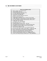
Macro Error Definition Table
01 Format error in extended command
02 Format error in conditional command
03 Unknown command in expression evaluation
04 Unknown command in update expression
05 Numeric variable range error
06 Scan sequence range error
07 External alarm range error
08 Auxiliary control output range error
09 Invalid numeric evaluation error
10 Macro timer range error
11 Macro timer command error
12 Macro timer period error
13 System macro range error
14 Unknown video output channel
15 Unknown video input source
16 Invalid external alarm control logic
17 Invalid auxiliary output control logic
18 Invalid camera disable logic
19 Invalid PTZ speed
20 Unknown system constant error
21 Unknown text message command error
22 Invalid operator sign used with commands
23 invalid keyboard identification number
24 Invalid alarm stack entry i.e.: not an alarm macro
25 Invalid alarm display group (1
Ù
50) only
26 Macro string exceeds 255 characters
27 Conditional statement missing closed brackets
28 Invalid real time clock time or date definition
29 Invalid video source command
Summary of Contents for MAXPRO-Net
Page 12: ...Rev C xii HMXMU01018 10 06 Notes ...
Page 20: ...Rev C xx HMXMU01018 10 06 Notes ...
Page 28: ...Rev C 4 2 HMXMU01018 10 06 Notes ...
Page 42: ...Rev C 7 2 HMXMU001018 10 06 Notes ...
Page 46: ...Rev C 7 2 4 HMXMU001018 10 06 Notes ...
Page 52: ...Rev C 7 3 6 HMXMU001018 10 06 Notes ...
Page 56: ...Rev C 7 4 4 HMXMU001018 10 06 Notes ...
Page 62: ...Rev C 7 6 4 HMXMU001018 10 06 Notes ...
Page 72: ...Rev C 7 9 6 HMXMU001018 10 06 Notes ...
Page 105: ...Rev C 7 11 17 HMXMU001018 10 06 ...
Page 106: ...Rev C 7 11 18 HMXMU001018 10 06 ...
Page 107: ...Rev C 7 11 19 HMXMU001018 10 06 ...
Page 108: ...Rev C 7 11 20 HMXMU001018 10 06 ...
Page 109: ...Rev C 7 11 21 HMXMU001018 10 06 ...
Page 110: ...Rev C 7 11 22 HMXMU001018 10 06 ...
Page 111: ...Rev C 7 11 23 HMXMU001018 10 06 ...
Page 112: ...Rev C 7 11 24 HMXMU001018 10 06 ...
Page 125: ...Rev C 7 12 13 HMXMU001018 10 06 ...
Page 126: ...Rev C 7 12 14 HMXMU001018 10 06 ...
Page 127: ...Rev C 7 12 15 HMXMU001018 10 06 ...
Page 128: ...Rev C 7 12 16 HMXMU001018 10 06 ...
Page 129: ...Rev C 7 12 17 HMXMU001018 10 06 ...
Page 130: ...Rev C 7 12 18 HMXMU001018 10 06 NOTES ...
Page 146: ...Rev C 7 15 12 HMXMU001018 10 06 Notes ...
Page 168: ...Rev C 7 19 2 HMXMU001018 10 06 HONEYWELL Copyright Honeywell Subject to change without notice ...
Page 170: ...Rev C 7 20 2 HMXMU001018 10 06 ...
Page 174: ...Rev C 8 4 HMXMU001018 10 06 8 3 PT321 CONNECTIONS ...
Page 175: ...Rev C 8 5 HMXMU001018 10 06 8 3 PT321 CONNECTIONS CONTINUED ...
Page 176: ...Rev C 8 6 HMXMU001018 10 06 8 4 PT323 CONNECTIONS ...
Page 177: ...Rev C 8 7 HMXMU001018 10 06 8 5 PT324 CONNECTIONS ...
Page 178: ...Rev C 8 8 HMXMU001018 10 06 8 6 PT325 CONNECTIONS ...
Page 179: ...Rev C 8 9 HMXMU001018 10 06 8 7 PT327 CONNECTIONS ...
Page 180: ...Rev C 8 10 HMXMU001018 10 06 8 8 RD390 LENS CONTROL EMULATOR CONNECTIONS ...
Page 181: ...Rev C 8 11 HMXMU001018 10 06 8 9 I O MODULE D25 CONNECTIONS ...
Page 182: ...Rev C 8 12 HMXMU001018 10 06 8 9 I O MODULE D25 CONNECTIONS CONTINUED ...
Page 198: ...Rev C 10 2 HMXMU001018 10 06 Notes ...


