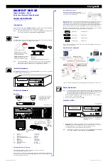
MAXPRO
®
NVR XE
(Xpress Edition)—Rev B
Entry Level Network Video Recorder
Quick Install Guide
Document 800-16129V4 – Rev A – 03/2017
Introduction
Welcome to your new Honeywell MAXPRO
®
NVR XE.
This guide helps you set up the NVR right
out of the box. Before installing your NVR, please read this guide carefully.
Note
Translated Quick Install Guides can be accessed on your MAXPRO NVR unit after logging
in, by clicking on
Start
menu
Honeywell
Quick Install Guides
.
Unpack
Check that the items received match those listed on the order form and packing slip. The packing
box should include, in addition to your NVR unit and this guide:
Install the Hardware
Mount the MAXPRO NVR XE Unit
Mount the MAXPRO NVR XE unit on a flat surface, horizontally
or vertically, using the supplied chassis feet.
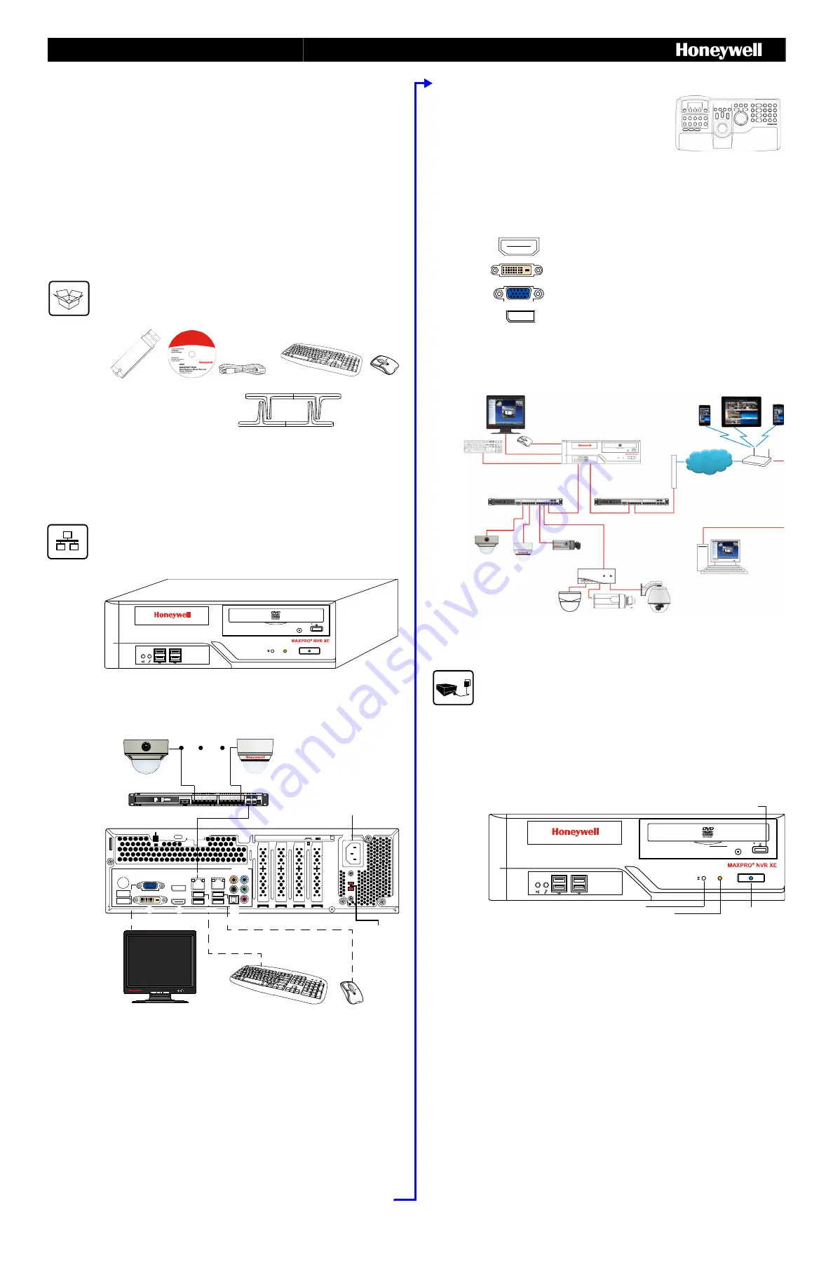
Connect the Hardware
Rear Panel
Switching the Power Preference
The MAXPRO NVR XE power rating is 115V/230V AC, 7/4 A, 60/50 Hz, 300 W.
The recommended power input is 110-120 V.
In some regions users may require the use of a 230 V AC power input. In this case, flip the power
input preference switch on the back of the MAXPRO NVR XE unit (see the diagram of the back panel
above for the location of the switch).
Chassis feet
Not shown
:
MAXPRO NVR DDNS Installation Instructions
Recovery USB Flash Drive
MAXPRO NVR Client Software
(Single Site) and Server Software
DVD (includes manuals)
MAXPRO Viewer Multi-Site Viewing
Softwar
e
Kit (includes DVD and
Getting Started Guide). Not shown.
Note
Other peripheral hardware (owner supplied) will also be needed for your installation
(such as cameras, network PoE switch for the camera network, network switch for a
client workstation network, a monitor, and an optional keyboard controller).
Connect supplied keyboard
and mouse before powering
up the NVR.
Connect up to 16 IP cameras to
a camera network PoE switch
and the switch to the LAN1
camera network port.
Connect a local monitor
to one of the monitor
outputs.
#
Connector
Connects to...
1
VGA Port
VGA monitor
2
Display Port
DP monitor
3
LAN1 - Camera Network Port
Network
4
LAN2 - Client/Workstation Network Port
Network
5
DVI-D Port
DVI monitor
6
HDMI Port
HDMI monitor
7
USB Ports (x4)
Various devices
8
S/PDIF (Optical)
Not used
9-13
Audio inputs and outputs
Not used
14
AC Power
Electrical outlet
Connect power cord
3
5
14
4
8
9-13
2
1
6
7
Power
preference
switch (to
switch
between
115 V and
230 V inputs)
Rear Panel Connections
Keyboard Controller (Optional)
Follow the
documentation that was included with your IP keyboard
controller to connect it to the NVR.
Network Connections
Connect a network PoE switch to the camera network port at the rear of the
MAXPRO NVR. Connect your cameras to the network PoE switch with CAT5 Ethernet cables.
Optionally, connect the client workstation network port to your client workstation network via a
network switch. This allows remote access to your NVR. The default client workstation network IP
address must be changed to an available static IP address on your client workstation network.
Monitor(s)
The MAXPRO NVR XE comes with built-in graphics and four types of monitor outputs.
The unit supports connection of a single monitor using one of the outputs.
The recommended resolution for your monitor is 1280 x 1024 pixels (minimum 1024 x 768) and
display colors of at least 32 bit.
Dual Network Configuration
Contact your dealer to purchase Honeywell and third-party IP and analog cameras and encoder.
Power Up the Unit
Note
Honeywell recommends using an uninterruptible power supply (UPS) for the NVR unit, the
camera network switch, and the cameras to ensure that the NVR can continue to record
video during a power outage or during transient power events. If you need to monitor
video during a power outage, consider a UPS for the monitor as well.
1.
Before powering up the NVR, turn on camera(s) and other devices — such as a network
switch or router — connected to the NVR.
2.
Press the power button on the front of the NVR.
Front Panel LEDs
3.
After powering on the unit, you are prompted to log on. The Default user is user name:
NVR-Admin
, password:
Password$123
. The user name and password are case sensitive.
You will be prompted to create a new password the first time that you log in.
The setup wizard starts automatically but may take two minutes.
Note
Translated Quick Install Guides can be accessed on your MAXPRO NVR unit after logging
in, by clicking on
Start
menu
Honeywell
Quick Install Guides
.
HDMI Output
to HDMI monitor
DVI-D Output
to DVI monitor
VGA Output
to VGA monitor
Display Output
to DP monitor
Local Monitor (not supplied)
Mobile Devices
MAXPRO
®
NVR XE
Router/
Firewall
Wireless
Router
Network
Client Workstation
Camera Network PoE Switch
Client Workstation Network Switch
Honeywell and Third-Party
IP Cameras
Encoder
H4D2F1
HD4HDIH
H3D2F1
HD3HDIH
HCD2F
HCD5HIH
Camera Network Port
(default 192.168.1.101)
Client Workstation Network
Port (default 172.25.254.101)
Analog Cameras
CAT5e
CAT5e
CAT5e
CAT5e
CAT5e
CAT5e
CAT5e
CAT5e
USB
USB
VGA/DVI-D/HDMI/DP
Power button with
Power LED (blue)
HDD activity
(Will flash amber when the
drive is in use)
Reset switch
Open CD/DVD-ROM
drive tray


