background image


Installation Instructions


P00180-02-0G0-09


EMBSC.00.0V05.xx


Subject to change 

without notice


2017-05-22 


Control panel


MB-Secure 1000/2000/3000/4000/5000/6000


Summary of Contents for MB-Secure 1000

Page 1: ...Installation Instructions P00180 02 0G0 09 EMBSC 00 0V05 xx Subject to change without notice 2017 05 22 Control panel MB Secure 1000 2000 3000 4000 5000 6000 ...

Page 2: ......

Page 3: ...Connect to earth line and open earthing bridge 23 3 9 3 Connect to own system earth and leave earthing bridge closed 23 3 10 Lines 24 3 10 1 Cables to signalling devices 24 3 10 2 BUS lines 24 3 10 3 Sample cable calculation for users 29 3 11 Special notes on installation and planning 31 3 12 Main zone extension via IB2 in remote housing as per VdS 32 4 Start up procedure 33 4 1 Preparations befor...

Page 4: ... alarm control panel and switch the power on They contain important notes on installation programming and operation The control panel is produced using the latest technology Operate the control panel only in accordance with the instructions and when it is technically perfect and has been correctly installed in accordance with the specifications The manufacturer is not liable for damage caused by i...

Page 5: ...B Secure 1000 Computer connection PCB Item no 013820 MB Secure 2000 Computer connection PCB Item no 013830 MB Secure 3000 Computer connection PCB Item no 013840 MB Secure 4000 Computer connection PCB Item no 013850 MB Secure 5000 Computer connection PCB Item no 013860 MB Secure 6000 Computer connection PCB Item no 013870 MB Secure motherboard Item no 013810 Computer connection PCB without specifie...

Page 6: ...ecure 2000 Item no 013830 Siren module MB Secure Item no 013920 Control panel housing ZG20 Item no 013730 Power supply charger unit 12 V 18 Ah Item no 013970 LCD operating unit Item no 013001 MB Secure 2000 starter bundle LCD plus transmission device Item no 013833 Computer connection PCB MB Secure 2000 Item no 013830 Siren module MB Secure Item no 013920 Control panel housing ZG20 Item no 013730 ...

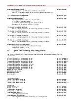
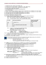
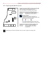
Page 7: ... battery space 1 x 3 4 Ah 1 5 Options for control panel configuration The following are the options that can be used depending on the housing dimensions and system specifications Power supply charger unit 12 V DC 17 Ah Item no 010686 01 Power supply charger unit 12 V DC 32 Ah Item no 010690 01 Power supply charger unit 12 V DC 40 Ah Item no 010690 02 Power supply charger unit 12 V DC 80 Ah Item no...

Page 8: ...ot be possible to tamper with the connecting cables without causing mechanical damage to the housing VdS guidelines 2311 Starting from approximately the first quarter of 2016 the doors of housings ZG 2 item no 013740 and ZG 3 1 item no 013750 will be supplied with an opening for installing a lock insert An individually keyed lock insert part no 028051 should be used for VdS compliant installations...

Page 9: ...g provides space for 2 batteries with max 17 Ah According to VdS guidelines the batteries are to be secured using a fixing strap 055280 2 4 Control panel in the ZG 4 Emergency power supply The housing provides space for 2 batteries with max 65 Ah According to VdS guidelines the batteries are to be secured using a fixing strap 055280 ...

Page 10: ... see the operating manual IQ PanelControl for MB Secure Chapter Help Password unknown Switches Setting OFF Setting ON S1 Manual release via TouchCenter Tuxedo TouchCenter Plus for access with IQ PanelControl or macro function Permanent release for access with IQ PanelControl S2 Factory use setting OFF must not be changed S3 Normal Mode Reset Mode Configuration does not get loaded IP address comes ...

Page 11: ...2 Modulbus RS 485 terminal programming jumpers Controller 1 Exclusive wired connection data bus connection 17 REVISION key If programmed using IQ Panel Control all alarm notifications within this main zone are cleared when the revision button is pressed This clearing is necessary to return the control panel to the alarm state and close the control unit housing again following maintenance for examp...

Page 12: ... to EN 50131 Grade 3 in relation to response in case of failure of periodic communication with 60 s to prevent the positive drive and 100 s to tamper or fault Messages are recognized within 200 ms and indicated within 10 seconds 2 5 1 Directly connectible Modulbus RS 485 reader The following table shows which reader types can currently be connected directly to the Modulbus RS 485 controller Item n...

Page 13: ...nd connection PE to the mounting bottom 15 BUS wire shields Important Direct connection to the contact area for ground connection 16 Connection for potential separation module 026595 10 17 BUS supply voltage additional connection in case of increased number of wires 18 BUS 2 RS 485 connection RS 485 in preparation Exclusive wired connection data bus connection 19 Supply voltage for module 20 Drill...

Page 14: ...56 10 Position B Signalling device 048700 048720 Monitoring resistors If signaling device 160455 10 160456 10 is connected the following monitoring resistors in the signaling device must be changed R1 10k 4k7 R2 4k7 12k1 R3 0R 12k1 The corresponding resistors can be found in the accessories pouch for the MB Secure Siren module Programming connection P7 interface operating mode Position A Interface...

Page 15: ...mpletely with IQ PanelControl Systems designed according to VdS class C have to be operated with an integrated transmission device via serial interface Operation of a DS 6700 DS 6750 transmission device in combination with the MB Secure control panel firmware version V05 xx firmware version V07 or higher for the transmission device is absolutely necessary 1 Plug for connection cable I BUS 2 V 24 i...

Page 16: ...e 18 Input channels e1 e8 19 Semiconductor outputs parallel indicators 20 Connection for indicator PCB 21 Jumper J5 22 Headphone connector socket 23 Microphone connector socket 24 LEDs Ethernet status 25 Jumper J6 26 Jumper J1 to J4 27 LEDs Device status Not relevant for MB Secure applications When connecting via the serial interface at most 1 module can be used for each control panel You can find...

Page 17: ...cording to VdS category C have to be operated with an integrated transmission device via serial interface Operation of a DS 7700 transmission device in combination with the control panel MB Secure firmware version V05 xx requires firmware version V09 or higher for the transmission device is absolutely necessary 1 Plug for connection cable I BUS 2 V 24 interface for RFW 4000 3 Reset button 4 Serial...

Page 18: ...nnection connection to NT 19 ISDN connection S0 BUS for further end units 20 Input channels e1 e8 21 Semiconductor outputs for parallel indicators 22 Connection for indicator PCB 23 Jumper J5 24 LEDs ISDN status 25 Jumper J7 26 Jumper J8 27 Jumper J9 28 LEDs Ethernet status 29 Jumper J10 30 Jumper J1 to J4 31 LEDs Device status Not relevant for MB Secure applications When connecting via the serial...

Page 19: ...it is equipped with a fault current safety switch FI switch the power supply must be assigned its own FI switch capable of carrying overload current The fuse and the FI switch should be located within the protection zone If the power supply of the intrusion detector control panel is not part of the control panel it should be installed mutually screwed right next to the control panel without any ga...

Page 20: ...t be complied with 3 4 Installing power supply unit and battery in housing ZG20 One of the three mounting screws for the housing ZG20 is behind the power supply charger and therefore the housing must first be mounted on the wall Then the power supply charger 013970 is to be attached in the lower left section of the housing using the three screws provided for this purpose In order to attach the bat...

Page 21: ... 100 mA BUS 2 Comfort Touch Color operating unit 012575 10 170 mA 540 mA BUS 2 TouchCenter Tuxedo graphical operating unit 013002 160 mA max 310 mA BUS 2 TouchCenter Plus graphical operating unit 013003 004 005 140 mA max 260 mA BUS 2 motion detector SCM 3000 3 mA 8 mA BUS 2 BUS 1 motion detector Viewguard DUAL AM 033442 20 4 6 mA 8 6 mA BUS 2 BUS 1 motion detector Viewguard DUAL 033443 20 4 6 mA ...

Page 22: ...20 Ah If sirens or a flash lamp for example are used as signaling devices allowance can be made for the reserve energy to activate the signaling device by increasing the total current consumption by 1 mA With this we have following calculation 60 hours x 251 mA 15 06 Ah The accumulator capacity selected remains sufficient 3 8 Connection of multiple power supply charger units Please note that when ...

Page 23: ...it offers the best protection against wireline faults and faults that occur due to cable shield discharges However it should be adopted only if PE and N are installed separately modern earthing and the earth line is guaranteed not to cause low or high frequency signals 3 9 2 Connect to earth line and open earthing bridge The brass rail shield terminal block at the cable inlet serve as a point of s...

Page 24: ...r supply for BUS users 0 V wire Return cable reference potential for BUS users Data cable A B Data exchange UE cable Additional cable for supply of power to BUS users with high power consumption In designing cable cross section areas for 12 V DC and 0 V the current consumption of the users connected must be the starting point Besides the base power for users the switching current sometimes require...

Page 25: ...m 12 V DC and 0 V care must be taken to ensure that the maximum loss of potential does not exceed 0 5 V DC The maximum cable length between the control panel and the farthest BUS user is 1000 meters For bus data cables the 2nd wire in the respective pair of wires must always be laid to 0 V Always increase the cable cross section for 12 V DC and 0 V using complete pairs of wires so that one wire is...

Page 26: ...H ST H J 2Y ST Y Cable diameter 0 6 mm and 0 8 mm Different cables should not be used together Star quad can be used J 2Y ST Y Maximum line length 2000 m in total The control panel can occupy any position on the BUS Terminating resistors 120 Ohm have always to be placed at the end of the lines 1 intermediate branch is permitted it must not exceed 40 m in length Supply lines to the participants mus...

Page 27: ...ers are operated in IB2 mode the terminating resistors on the computer connection PCB of the control panel and the connection PCB of the BUS users are to be set as follows Likewise the maximum line lengths are to be observed The control panel is located at the start of the BUS line The control panel is not the start or end point of the BUS line General line lengths ...

Page 28: ...28 Installation Instructions MB Secure 1000 2000 3000 4000 5000 6000 Terminating resistors and line lenghts of Modulbus RS 485 Shield connection Picture of the shielding connection terminal example ...

Page 29: ...he max loss of potential is 0 5 V DC A telephone cable is a copper cable with a conductivity of k Kappa 56 m Ωmm2 Calculation of line resistance RL Line resistance UV max permissible voltage drop I Current consumption of all BUS users on a BUS connection branch Calculation of cross section required A wire cross section per connection RL line resistance 12 V DC and 0 V total k specific conductance ...

Page 30: ...rs to the sample calculation According to the calculation the vertical pointer at the point of intersection shows 150 mA 150 m or just below 6 wires of diameter 0 6 mm or more than 3 wires of diameter 0 8 mm Rounded up to whole wires this comes to 6 wires with a wire diameter of 0 6 mm or 4 wires with a wire diameter of 0 8 mm as yielded by the calculation Diagram Determining the cross section num...

Page 31: ...llowed according to VdS The connection between the control panel and the transmission device is made via the serial interface or via relay When using the DSxx we recommend the serial interface When using another transmission device the absence of feedback must be guaranteed Additional relay assemblies may have to be installed BUS 2 operating units A maximum of 10 operating units can be connected t...

Page 32: ...te housing the installation of the IB2 to the expander module must be implemented in protected installation see VdS 2311 In addition the IB2 BUS expansion module s must be assigned to the contral panel main zone in IQ PanelControl under the System Main zones Main zones Detector groups Detector group X State evaluation tab This is irrespective of the main zones for which the IB2 BUS extension is to...

Page 33: ...ol panel in order to detect any line interruptions or short circuits Ensure that there is no earth fault Cover contacts of system components and the control panel must be closed Simulate cover contacts of the control panel possibly using a shorting bar or keep closed using a magnet If programmed with tamper monitoring flash lamps and sirens must be correctly installed BUS user addressing must have...

Page 34: ...re only in de energized state Alternatively the USB stick can be enabled via the service interface Button Unmount before removing it 5 Maintenance 5 1 General The control panel must be maintained in accordance with the appropriate guidelines Maintenance is required at least once a year We recommend maintenance in accordance with VDE 0833 This alone will ensure operational readiness of the system 5...

Page 35: ...ware update is completed the system configuration must be converted and restored to the contral panel Procedure for Update Place the USB stick with the latest firmware file in the USB host port of the computer connection PCB Press the Abort key The four Status information LEDs light steadily for 2 seconds Press the abort key once again during this time The control panel resets itself The four Stat...

Page 36: ...to EN 50131 1 Class II Operating temperature range 5 C to 45 C Storage temperature range 25 C to 70 C Relative humidity max 93 non condensing Optional control panel housing Dimensions W x H x D in mm ZG 20 460 x 382 x 85 ZG 2 350 x 300 x 152 ZG 3 1 500 x 300 x 210 ZG 4 580 x 640 x 300 Weight without options ZG20 around 5 kg ZG2 around 8 kg ZG3 1 around 13 kg ZG4 without 19 front panels around 28 k...

Page 37: ...lation Instructions MB Secure 1000 2000 3000 4000 5000 6000 37 7 Connection diagrams 7 1 Connection of MB Secure Siren module Connection and activation of signaling devices 160455 10 160456 10 in preparation ...

Page 38: ...38 Installation Instructions MB Secure 1000 2000 3000 4000 5000 6000 7 2 Connection of compact alarm unit and PCL Diagram Connection diagram of compact alarm unit and PCL in the protective housing ...

Page 39: ... group using a zero potential relay contact and simple contacts without external power supply e g magnetic contacts Z Sensors Detectors that draw their supply voltage from the voltage of the detector group When a detector is activated the detector group voltage is loaded such that the control panel can carry out an evaluation Diagram Wiring diagram for magnet contacts Diagram Wiring diagram for gl...

Page 40: ...d information on the connection of individual components to the evaluation unit in the Mounting and Connection Instructions IDENT KEY IK3 evaluation unit 023312 10 To operate an IDENT KEY IK3 evaluation unit with the MB Secure control panel the evaluation unit must be mandatory at software version V12 or higher Operating mode Centralized Authorization number of IDENT KEY ID data carriers 1024 When...

Page 41: ...Installation Instructions MB Secure 1000 2000 3000 4000 5000 6000 41 7 5 Connecting an electromechanical blocking element 019030 20 019033 Diagram Connection of an electromechanical blocking element ...

Page 42: ...42 Installation Instructions MB Secure 1000 2000 3000 4000 5000 6000 7 6 Connection diagram of transmission device DS 6700 DS 6750 057864 057865 7 7 ...

Page 43: ...Installation Instructions MB Secure 1000 2000 3000 4000 5000 6000 43 7 7 Connection diagram of transmission device DS 7700 057651 20 7 8 ...

Page 44: ... Instructions MB Secure 1000 2000 3000 4000 5000 6000 7 8 Connection diagram of Computer Connection PCB Controllers 1 4 For BUS 2 operation connection B should not be used Connection diagram of Computer connection PCB ...

Page 45: ...plied via the external load connections on the power supply unit In addition the fuse for the corresponding bus branch is to be removed on the computer connection PCB for 2 The external load connection on the computer connection PCB may not exit the housing It can be used to connect a transmission device inside the housing for example for 3 A separately routed BUS branch has to be used for each pr...

Page 46: ...970 Protective earthing When the power supply unit 013970 is mounted in a metal housing a conductive connection must be established between the protective earth connection E of the power supply unit and the housing The main connection of the protective conductor must be installed at the correspondingly marked terminal ...

Page 47: ...Installation Instructions MB Secure 1000 2000 3000 4000 5000 6000 47 Notes ...

Page 48: ...Honeywell Security Group Novar GmbH Johannes Mauthe Straße 14 72458 Albstadt Germany www security honeywell com P00180 02 0G0 09 2017 05 22 2017 Novar GmbH ...

Reviews: