HONEYWELL
7157 585
EN1B-0204GE51 R0403
R7426D
UNIVERSAL INPUT CONTROLLER
INSTALLATION & START-UP INSTRUCTIONS
Fig. 1. Temperature Controller
Contents
General................................................................................ 1
Before Installation Note ....................................................... 1
Mounting .............................................................................. 1
Wiring .................................................................................. 2
Power Supply and Grounding.............................................. 2
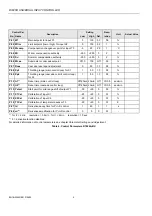
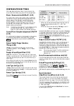
Configuration and Control Parameters ................................ 3
Configuration Settings ......................................................... 5
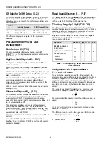
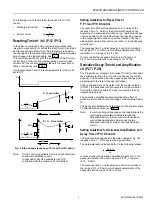
Parameter Settings and Adjustment .................................... 6
Operating Overview ............................................................. 9
GENERAL
This document provides instructions and procedures for
installing and starting up the Micronik 200 R7426D controller.
No special tools are required for mounting and installation.
The user interface and LC display allows accurate and easy
parameter setting and output adjustment.
BEFORE INSTALLATION NOTE
•
Visually inspect equipment for shipping damage.
Report any damage to the appropriate Honeywell
representative.
•
Refer to job drawings for specific installation
information and mounting location.
•
Verify the controller will be adequately separated from
the main power supply, relays or other equipment
which can possibly generate electromagnetic inter-
ference.
•
Verify that the ambient temperature and the humidity
at the controller will be within the limits of 0...50
°°°°
C
(32...122
°°°°
F) and 5 to 95% rh.
•
Use shielded wiring in areas with high EMI.
•
All wiring should be separated from power lines by at
least 150mm (6’’).
•
Do not install controllers near frequency converters
or other high frequency sources.
MOUNTING
The controller can be mounted in an electric cabinet or an
other suitable enclosure. It is suitable for back panel, DIN rail,
wall or front panel mounting with an additional available front
panel mounting frame. The mounting sequence of each as
well as dimensions and panel cut-out is illustrated in the
mounting instruction sheet EN1B-0202GE51 supplied with
the controllers.
If the compensation sensor signal (T3) is received from
another controller (parallel connection of compensation
sensor inputs), the jumper W303 must be cut before
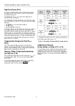
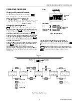
mounting the controller (see Fig. 2). This disconnects the
sensor from the internal power supply.
MicroniK 200


