R7426D UNIVERSAL INPUT CONTROLLER
EN1B-0204GE51 R0403
6
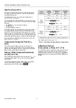
Off Delay for On/Off Output (C.26)
The On/Off output is controlled by the Plant / System On/Off
input and provides an Off switching output with adjustable
delay time e.g. to operate the fan still for a certain time after
humidification.
On/Off
Input
Controller Function
On/Off Output: Delay
On
Normal control
Off
→
On: 0 min
Off
Output Y1 = 0%
On
→
Off: 0...60 min
The off time delay can be adjusted by the parameter
OffDelay
.
PARAMETER SETTINGS AND
ADJUSTMENT
Main Setpoint W1 (P.01)
The main setpoint is either set by the parameter
W1
(
CPATYP
= 0 or 1) or by the external setpoint potentiometer
(
CPATYP
= 2).
High/Low Limit Setpoint W
lim
(P.02)
For high or low limit control, the control parameter
W
lim
is
used as setpoint.
During limit control, the throttling range
Xp2
and reset time
tr2
are active.
Limit control will be active only, if the X2 signal (
X2ext
= 0) is
available or alternatively the sensor X1 (
X2ext
= 1) is used
also for limit control.
For cascade control the limit setpoint
W
lim
determines the
control point at which the submaster setpoint
(
W
cas
)
maintains the limit value and is not shifted anymore by the
master control loop.
High or low limit control is in accordance with the parameter
LimTyp
(C.13).
Submaster Setpoint W
cas
(P.06)
The R7426D controller provides cascade control which uses
two control loops, master and submaster to maintain the
master setpoint CTRP1. Cascade control will be active, if
sensor X2 is connected and the control parameter
W
cas
is set
to any value other than Off.
This adjustment sets the control point of the submaster
control loop, cascade input (X2), at zero deviation of the
master control loop. If the controlled input X1 deviates from
the master setpoint CTRP1, the submaster setpoint
W
cas
is
automatically altered (CTRP2
)
.
Cascade control is disabled, if the submaster setpoint
W
cas
is
set to Off.
Low limit of CTRP2 is performed if control parameter
LimTyp
= 0 and high limit of CTRP2 is performed if control
parameter
LimTyp
= 1.
Reset Span Adjustment R
cas
(P.07)
The reset span adjustment
R
cas
determines the reset effect in
%, the submaster setpoint
W
cas
is altered, if the main input
(X1) deviates by 50% of the throttling range
Xp1
.
Throttling Range Xp1 / Xp2 (P.08 / P09)
Throttling range X
p
adjustment determines the controller
variable change, required at the main sensor (X1) and limit or
cascade sensor (X2) to operate the output device from full
open (100%) to full closed (0%) or vice versa.
Xp1
is the throttling range for the main control loop,
Xp2
is
the throttling range for limitation or cascade control
(submaster control loop).
Application
Sens. Xp1 Xp2 tr1 tr2 vd/td
R7426D Controller
Main Control
X1
x
x
x
High or Low Limit Control
X2
x
x
x
Cascade Control
Master
X1
x
x
Submaster
X2
x
x
x
Table 6. Throttling Range, Reset and Derivative
Time Reference
Setting Guidelines for Proportional Band of
P, P+I and P+I+D Control
To estimate the proportional band (throttling range X
p
) for
stable control under all different load conditions the control or
correcting range X
h
of the controlled variable by the final
controlling element has to be known. This is the maximum
difference in the controlled variable between the fully closed
and fully open position of the final controlling element (e.g.
valve).
The proportional band X
p
for discharge air control can be
calculated by using the following rule-of thumb formula:
X
p
=
X
h
5
For room control the following rule-of-thumb formula can be
used:
X
p
=
X
h
10
In P+I or P+I+D control the same proportional band can be
used as for P control.
The following rule-of-thumb formula are used for P+I control:
•
Discharge air control
X
p
=
X
h
4 5
...
•
Room
control
X
p
=
X
h
8 10
...


