Midas
®
Gas Detector
7-10
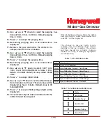
14. Press ‘X’ to return to set-up, calibration and test
menu selection.
15. Press ‘X’ again to return to normal operation.
Table 7-3. Fault relay configuration options.
Fault Relay Configuration
Relay 1
Relay 2
Relay 3
Instrument Fault Only
(1FLt)
Alarm 1 Alarm 2
Instrument
Fault
Separate Fault Relays
(2FLt)
Any
Alarm
Maintenance
Fault
Instrument
Fault
Combined Fault Relay
(CmbF)
Alarm 1 Alarm 2
Any Fault
Network Remote
Control (nEtr)
Remote control of relays via Modbus/
TCP or LonWorks
®
Note
Remote control of the relays can be facilitated
using Modbus/TCP or LonWorks® control
from a centralized control system. In this
mode, the Midas® relays are only controlled
via the remote system when set to nEtr.
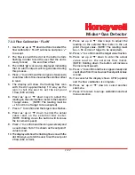
7.2.5 Set Calibration Interval ‘ CAL’
1. Select the set calibration interval ‘ CAL’
submenu and press ‘
3
’ to accept.
2. The flashing display shows the number of days
interval after a calibration that a calibration due
maintenance fault will be displayed.
3. Use the ‘
s
’ up or ‘
t
’ down buttons
t o c h a n g e t h e n u m b e r o f d a y s . ( I f
t h e c a l i b r a t i o n i n t e r v a l i s s e t b e l o w
‘001’ then ‘OFF’ will be displayed and no user
calibration interval will be activated and no
reminders displayed)
4. Press ‘
3
’ to update the change (UPdt displayed)
and return to step 1.
5. Press ‘
s
’ up or ‘
t
’ down to select another
submenu.
6. Press ‘X’ to return to set-up, calibration and test
menu selection.
7. Press ‘X’ again to return to normal operation.
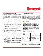
7.2.6 Set Date and Time ‘timE’
1. Select the set date and time ‘timE’ submenu and
press ‘
3
’ to accept.
2. The flashing display will show the current date
format mm:dd or dd:mm.
3. Use the ‘
s
’ up or ‘
t
’ down buttons to change
the date format.
4. Press ‘
3
’ to display the flashing current year
setting.
5. Use the ‘
s
’ up or ‘
t
’ down buttons to change
the year setting (between 2003 and 2030).
Summary of Contents for Midas
Page 7: ...Midas Gas Detector 1 1 1 Description ...
Page 9: ...Midas Gas Detector 2 1 2 Overview ...
Page 14: ...Midas Gas Detector 3 1 3 Default Configuration ...
Page 17: ...Midas Gas Detector 4 1 4 Installation ...
Page 41: ...Midas Gas Detector 5 1 5 Startup ...
Page 43: ...Midas Gas Detector 6 1 6 Operation ...
Page 53: ...Midas Gas Detector 7 1 7 Navigating Modes and Submenus ...
Page 74: ...Midas Gas Detector 8 1 8 Maintenance ...
Page 82: ...Midas Gas Detector 9 1 9 Pyrolyzer Module Options ...
Page 89: ...Midas Gas Detector 10 1 10 Optional LonWorks Interface Installation ...
Page 99: ...Midas Gas Detector 11 1 11 Troubleshooting and Fault Diagnosis ...
Page 102: ...Midas Gas Detector 12 1 12 REFLEX ...
Page 104: ...Midas Gas Detector 13 1 13 Internal Web Server ...
Page 106: ...Midas Gas Detector 13 3 Diagram 13 1 IPAddress setting in Windows XP ...
Page 129: ...Midas Gas Detector 14 1 14 Typical Installation Topologies ...
Page 132: ...Midas Gas Detector 15 1 15 Ordering Information ...
Page 136: ...Midas Gas Detector 16 1 16 Specifications ...
Page 139: ...Midas Gas Detector 17 1 17 Calibration and Bump Testing ...
Page 143: ...Midas Gas Detector A 1 A Modbus TCP Interface ...
Page 150: ...Midas Gas Detector B 1 B Gas Tables ...
Page 158: ...Midas Gas Detector C 1 C Warranty ...


