LED
Description
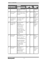
Specifies the operation status of the CPU module.
l
Green light: Implies the CPU operation is in ‘RUN’ mode either by any of
the following:
l
‘RUN/STOP’ switch in CPU set to RUN mode.
l
REMOTE ‘RUN’ operation through SoftMaster even when the local
switch is on ‘STOP’ mode.
l
Red light: The CPU operation is in ‘STOP’ mode either by any of the
following
RUN/STOP
LED
l
RUN/STOP switch in CPU set to STOP mode.
l
REMOTE ‘STOP’ operation through SoftMaster even when the local
switch is in ‘RUN’ mode.
l
Red Blink: Warning or error during ‘STOP’ operation (if an error occurs,
stop the ongoing operation).
REM LED
ON (YELLOW): ‘Remote enabled’ in case ’REMOTE’ switch is ‘ON’.
OFF: ‘Remote disabled’ in case ‘REMOTE’ switch is ‘OFF’.
ERR LED
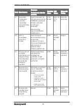
ON (RED): Error has occurred and CPU cannot operate normally.
OFF: Normal operation.
PS LED
(Programmable
Status)
l
Red ON:
l
‘User assigned flag’ is ‘ON’.
l
Operating in the error state by ‘operation proceeding in the error’
setting.
l
Module is detached or new module is installed in the state where
‘M.XCHG‘ switch is ‘ON’.
l
OFF: Normal operation
BAT LED
ON (Red): Battery voltage is low.
OFF: Normal operation.
CHK LED
l
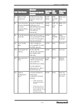
Red ON:
l
Setting is different from standard setting (it is possible to add/delete
[clear] by parameter).
l
‘Module change’ switch is set as ‘Module change’.
l
Operating in ‘DEBUG mode’.
l
‘Forced ON’ setting state.
l
‘Fault mask’, ‘SKIP’ flag is set.
l
Warning occurs during operation.
- 46 -
Chapter 3 - Plan and Install MLPLC

