background image

ML4105, ML4115, ML8105, ML8115 FAST-ACTING, TWO-POSITION ACTUATORS

63-2540—9

4

INSTALLATION

When Installing this Product...

1.

Read these instructions carefully. Failure to follow 

them could damage the product or cause a hazardous 

condition.

2.

Check the ratings given in the instructions and on the 

product to make sure the product is suitable for your 

application.

3.

Installer must be a trained, experienced service 

technician.

4.

After installation is complete, check out product 

operation as provided in these instructions.

IMPORTANT

All wiring must agree with applicable codes, 

ordinances and regulations.

WARNING

Electrical Power Hazard.

Line voltage can cause death or serious injury 

and short equipment circuitry.

Disconnect power supply before installation.

CAUTION

Electrical Shock or Equipment Damage Hazard.

Low voltage can shock individuals or short 

equipment circuitry.

Disconnect power supply before installation.

Location and Mounting

The ML4105, ML4115, ML8105 and ML8115 DCA are 

designed to open a damper by driving the damper shaft in 

either clockwise 

 or counterclockwise 

 direction. 

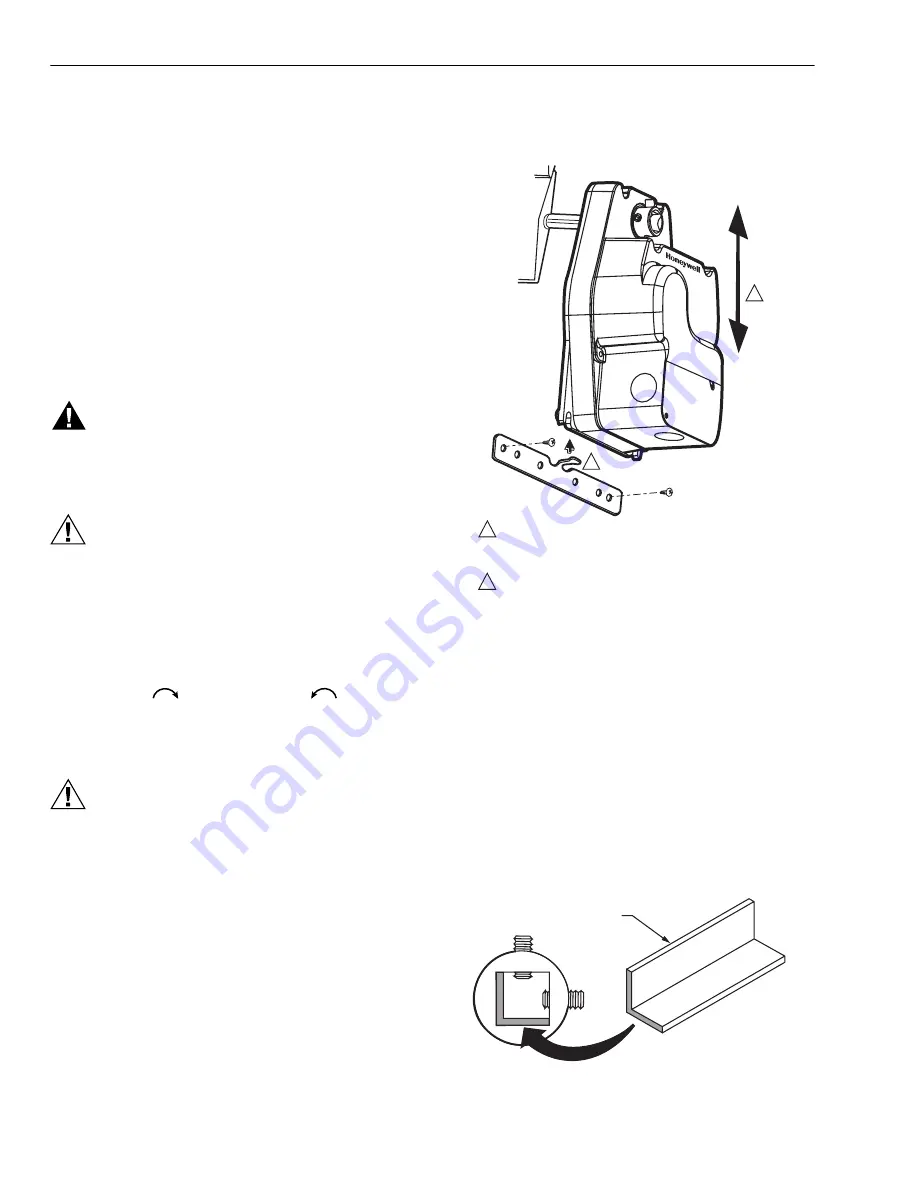
The actuator housing has two slots on the bottom that, with a 

205649 Mounting Bracket, secure it flush to a damper box 

(see Fig. 2). When mounted correctly, these slots allow the 

actuator to 

float

 without rotating relative to the damper shaft.

CAUTION

Equipment Damage Hazard.

Tightly securing actuator to damper housing can 

damage actuator.

Mount actuator to allow it to float along its vertical axis.

NOTE: ML4105, ML4115, ML8105, and ML8115 Actuators 

are shipped in the fully closed position.

Fig. 2. Mounting actuator to damper housing.

Preparation

Before mounting the actuator onto the damper shaft, 

determine the damper shaft size (3/8 in. to 1/2 in. 

[10 mm to 13 mm]).

If damper shaft is 3/8 in. (10 mm) round or square, use part 

number 201391 Shaft Adapter 

(not supplied with actuator)

Place adapter opposite set screws (see Fig. 3).

NOTE: The damper shaft adapter centers a 3/8 in. (10 mm) 

damper shaft in the hub. Failure to use adapter can 

cause mounting screws to loosen. A 1/2 in. (13 mm) 

damper shaft does not require an adapter.

Fig. 3. Using damper shaft adapter for 

3/8 in. (10 mm) damper shafts.

M13054A

ENSURE THAT MOUNTING ASSEMBLY PREVENTS ACTUATOR 

ROTATION AND ALLOWS ACTUATOR TO FLOAT ALONG 

INDICATED AXIS.  WHEN TOO TIGHT, THE RESULTING  BINDING 

CAN DAMAGE THE ACTUATOR OR REDUCE TORQUE OUTPUT.

ACCESSORY MOUNTING BRACKET IS NOT SUPPLIED WITH 

THE ACTUATOR.

1

1

2

2

SH

A

FT 

A

D

A

PTER

M2064

Summary of Contents for ML4105

Page 1: ...al spring return ensures level of return torque Fifteen second spring return timing No special cycling required during long term holding See Operation section No audible noise during holding Patent pending design eliminates need for limit switches to reduce power consumption Models available for 24 120 and 230 Vac Ninety five degree angle of rotation Actuator holds rated torque at reduced power le...

Page 2: ...28 UNF set screws Use 1 8 in Allen wrench to tighten set screws ML4105C D Four 3 mm set screws Use 3 mm Allen wrench to tighten set screws ML4115 ML8115 Two 1 4 28 UNF set screws Use 1 8 in Allen wrench to tighten set screws IMPORTANT Honeywell does not recommend using linkages with these actuators because side loading of the output hub reduces actuator life Temperature Ratings Ambient 0 F to 130 ...

Page 3: ...ication NFPA recommends periodic examination of each fire smoke damper semi annually or annually to ensure proper performance Design Life at Rated Voltage 60 000 full stroke cycles Approvals See Table 2 Environmental Protection Ratings See Table 3 Accessories 201391 Shaft Adapter for 3 8 in shafts not supplied with actuator 205649 Mounting Bracket not supplied with actuator Table 2 Approvals Table...

Page 4: ... the bottom that with a 205649 Mounting Bracket secure it flush to a damper box see Fig 2 When mounted correctly these slots allow the actuator to float without rotating relative to the damper shaft CAUTION Equipment Damage Hazard Tightly securing actuator to damper housing can damage actuator Mount actuator to allow it to float along its vertical axis NOTE ML4105 ML4115 ML8105 and ML8115 Actuator...

Page 5: ... lb in maximum 60 lb in torque Use 1 8 in or 3 mm Allen wrench see Specifications for details to tighten set screws Wiring See Fig 4 through 8 for typical wiring diagrams WARNING Electrical Power Hazard Line voltage can cause death or serious injury and short equipment circuitry Disconnect power supply before installation CAUTION Electrical Shock or Equipment Damage Hazard Low voltage can shock in...

Page 6: ... building IMPORTANT If the indicator turns black replace the actuator NOTE The actuator is designed to operate for 30 minutes during a one time excursion to 350 F 176 C CHECKOUT ML4105A B and ML4115A B 120 Vac model 1 Verify that the indicator has not turned black see Temperature Indicator section 2 Check damper position 3 Connect 120 Vac to the black and white leadwires to drive the damper to the...

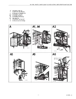
Page 7: ... DK Installasjonsinstruks N Installationsinstrukioner SF Asennusohje S Installations Instrukioner E Instrucciones de montage M11874 ASSEMBLY EINBAU MONTAGE MONTAGGIO MONTAGE MONTERE MONTERING ASENTAMINEN MONTERA MONTAJE D F I NL DK N FIN S E 24 VAC 120 VAC M11875 b a M11876 a b c d M12030 a b M11881 b a M11882 HEX 4mm MIN 45 lb in 5 1 Nm MAX 60lb in 6 8 Nm a b c A A1 A4 A3 A5 A2 A6 ...

Page 8: ...Drive North 35 Dynamic Drive Honeywell Building 1140 Brussels 480 Sawgrass Corporate Parkway Golden Valley MN 55422 Scarborough Ontario 17 Changi Business Park Central 1 Belgium Suite 200 M1V 4Z9 Singapore 486073 Sunrise FL 33325 National Fire Codes is a registered trademark of the National Fire Protection Association NFPA 24 VAC 120 VAC M11884 DISASSEMBLY AUSBAU DÉMONTAGE SMONTAGGIO DEMONTAGE AFM...

Reviews: