background image

PRODUCT DATA

® U.S. Registered Trademark
© 2004 Honeywell International Inc.
 All Rights Reserved 

63-2511—1

ML6194, ML6294

Non-Spring Return

Direct Coupled Actuators

APPLICATION

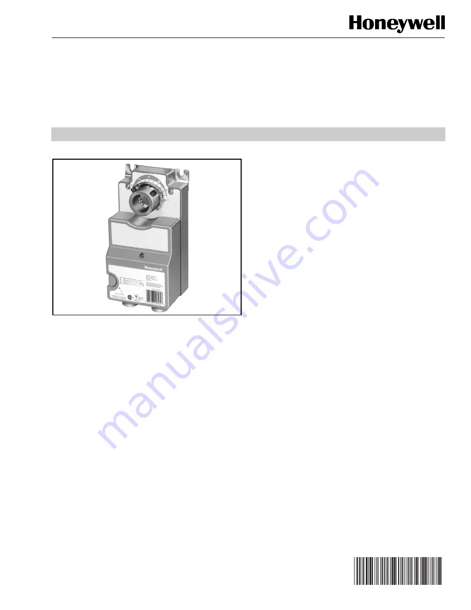
The ML6194 and ML6294 Non-Spring Return Direct Coupled 

Actuators (DCA) provide floating single-pole, double-throw 

(spdt) control of dampers or valves in heating, ventilating, and 

air conditioning (HVAC) applications. The ML6294 has an  

internal, electrically isolated feedback potentiometer that can 

be used to provide indication of motor output hub position or 

slave a Series 90 actuator.

FEATURES

• Mount directly on 1/2 in. to 3/4 in. (13 to 19 mm) round 

or square shaft. Mount on 1 in. (26 mm) round shafts 

with appropriate insert. All models shipped with 1 in. 

insert.

• 300 lb-in. (34 N•m) torque.
• Magnetic coupling eliminates need for mechanical 

stops or limit switch adjustments by limiting stall 

torque, which is dependent on temperature. Nominal 

stall torque at room temperature of 68°F (20°C) is 410 

lb-in.

• 95° stroke provides necessary compression of 

rubber/neoprene gaskets commonly used on 90° low 

leakage dampers.

• Declutch feature allows manual adjustment.
• 165 second synchronous timing can eliminate need for 

feedback position indication in closed-loop 

temperature control applications.

• Both single-point and three-point mounting 

compatibility to allow installation flexibility.

• Models available with or without time-out feature.

Contents

Application ........................................................................

1

Features ...........................................................................

1

Specifications ...................................................................
2

Ordering Information  ........................................................
2

Installation ........................................................................
4

Wiring ...............................................................................
6

Operation ..........................................................................
7

Checkout ..........................................................................
8

Troubleshooting ................................................................
8

Summary of Contents for ML6194

Page 1: ...fts with appropriate insert All models shipped with 1 in insert 300 lb in 34 N m torque Magnetic coupling eliminates need for mechanical stops or limit switch adjustments by limiting stall torque which is dependent on temperature Nominal stall torque at room temperature of 68 F 20 C is 410 lb in 95 stroke provides necessary compression of rubber neoprene gaskets commonly used on 90 low leakage dam...

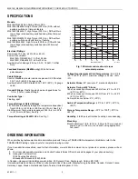
Page 2: ...Hz Power Consumption ML6194A C ML6294A C 5 VA at 24 Vac ML6194D F ML6294D F 6 VA at 24 Vac Auxiliary Switch Ratings 24 Vac 3 AFL 18 ALR 1A Pilot Duty Feedback Resistor ML6294 only 500 ohm linear potentiometer Cable Ratings Control Standard models include nonplenum UL CSA rated 30V 140 F 60 C 20 gauge cable Auxiliary Switch UL CSA rated 300V 194 F 90 C 18 gauge cable Conduit Fittings Plastic housin...

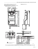
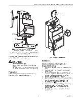
Page 3: ...hub sizes Dimensions See Fig 2 Fig 2 Approximate dimensions of ML6194 ML6294 Non Spring Return DCA and mounting bracket in in mm 9 32 7 3 PLACES 1 17 32 39 3 3 32 79 4 102 7 16 11 1 1 4 32 7 11 16 196 8 7 16 215 36 914 1 2 12 5 8 17 13 32 10 1 2 13 3 4 19 7 8 22 1 25 3 5 32 80 1 2 13 1 2 13 1 11 16 43 2 1 2 63 3 5 16 84 4 1 2 114 5 127 6 152 1 4 6 1 1 REMOVABLE RETAINING RING FOR HUB SLEEVE REMOVA...

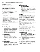
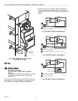
Page 4: ...ion will damage the actuator 1 Deteriorating vapors and acid fumes can damage actuator metal parts 2 Install actuator in areas free of acid fumes and other deteriorating vapors 3 Turning motor output hub by hand or wrench can damage internal gears 4 Ensure declutch button is depressed while manually turning hub Mounting The ML6194 ML6294 Non Spring Return DCA is designed with removable hub inserts...

Page 5: ... 2 Position actuator for best access to actuator shaft locking screw 3 Install mounting bracket see Fig 2 and adjust it to center mounting bracket tab in actuator slot Mark screw holes for installing mounting bracket on housing 4 Remove mounting bracket and actuator 5 Drill mounting holes for screws screws not provided 6 Place actuator and mounting bracket back into position over shaft and install...

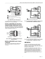
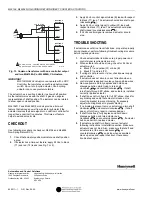
Page 6: ...on See Fig 6 through 9 for typical wiring diagrams Fig 6 ML6194A C typical wiring diagram Fig 7 ML6194D F typical wiring diagram Fig 8 ML6294A C typical wiring diagram M11273A MOUNTING BRACKET TO JUNCTION BOX UP TO 3 FT AWAY 30 30 0 60 60 90 L1 HOT L2 1 1 MOTOR 24 VAC B BLUE W YELLOW T2 BLACK ML6194A C M11283A POWER SUPPLY PROVIDE DISCONNECT MEANS AND OVERLOAD PROTECTION AS REQUIRED CONTROLLER L1 ...

Page 7: ...tilation flaps and louvers requiring up to 300 lb in torque The ML6194 and ML6294 Non Spring Return DCA are operated by an spdt floating controller When using an spdt floating controller actuator is driven toward fully open clockwise position when controller makes B contact and toward fully closed counterclockwise position when controller makes W contact It stops when neither contact is made L1 HO...

Page 8: ...ould stop TROUBLESHOOTING If actuator does not drive travel full stroke or operate properly during checkout perform following troubleshooting procedure before replacing actuator 1 Check actuator label to make sure proper power and control signal requirements are met 2 When actuator should be driving check for 24 Vac at actuator wires a Black T1 and yellow W or blue B b Black T1 and red T2 3 If vol...

Reviews: