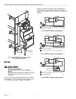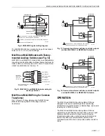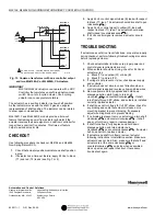
ML6194, ML6294 NON-SPRING RETURN DIRECT COUPLED ACTUATORS
63-2511—1
4
Device Weight:
3.0 lb (1.36 kg).
Noise Rating:
45 dBA maximum at 1 meter.
Position Indicator:
Mounted on actuator hub.
Actuator Design Life:
Full Stroke Cycles: 50,000.
Repositions:
1,500,000 minimum.
Approvals:
Underwriter’s Laboratories Inc. Component Recognized:
UL873, File No. E4436; Guide No. XAPX.
CSA Listed: File Number LR95329-17.
Meets UL94-5V plenum requirements.
Environment Protection Rating:
IP54 standard with shaft in
horizontal position.
Accessories:
205843B Hub Insert, 1 in. round, with retaining ring.
205856B Hub Insert, 3/4 in., round or square, with retaining
ring.
205849A Hub Insert, 5/8 in., round or square, with set screws.
205820A Three-point Mounting Kit.
205846 Crank-Arm Accessory.
205860 Remote Minimum Position Potentiometer.
205860A Remote Minimum Position Potentiometer, NEMA IV
rated.
INSTALLATION
When Installing this Product...
1.
Read instructions carefully. Failure to follow them could
damage the product or cause a hazardous condition.
2.
Check ratings and descriptions given in specifications to
make sure product is suitable for your application.
3.
Installer must be a trained, experienced service
technician.
4.
After installation is complete, check out product
operation as provided in these instructions.
WARNING
Explosion or Fire Hazard.
Can cause severe injury, death or property
damage.
A spark from the actuator or attached accessories
could ignite escaping gas or vapors. Install actuator in
areas free of escaping gas and other explosive
vapors.
WARNING
Electrical Shock or Equipment Damage Hazard.
Can cause severe injury, death or property
damage.
Disconnect power supply before installation. Actuators
with auxiliary switches can have more than one
disconnect.
CAUTION
Equipment Damage Hazard.
Wrong location or improper operation will damage
the actuator.
1. Deteriorating vapors and acid fumes can damage
actuator metal parts.
2. Install actuator in areas free of acid fumes and other
deteriorating vapors.
3. Turning motor output hub by hand or wrench can
damage internal gears.
4. Ensure declutch button is depressed while manually
turning hub.
Mounting
The ML6194/ML6294 Non-Spring Return DCA is designed
with removable hub inserts to accommodate specific shaft
sizes. Proper insert selection is necessary to avoid excessive
strain on output gear. All ML6194/ML6294 Actuators are
shipped with a one-inch hub insert. For field use, two hub
insert sizes are available (see Accessories section). A
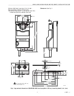
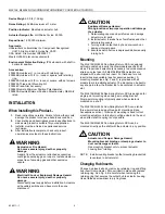
mounting bracket (see Fig. 2 and 3) is provided with all
models to aid in installing actuator. The bracket can be bent to
any shape to allow the bracket tab to be centered in actuator
slot.
The ML6194/ML6294 Non-Spring Return DCA is designed for
single-point mounting when using a mounting bracket.
Single-point mounting is typically used when actuator is
mounted on a shaft.
The ML6194/ML6294 Non-Spring Return DCA can also be
three-point mounted using three-point mounting kit (see
Accessories section). Three-point mounting is used for foot
mounting actuator or internally mounting actuator in the duct
when direct shaft coupling is not possible.
The ML6194/ML6294 Non-Spring Return DCA can be
mounted directly on the shaft with the actuator in any position.
CAUTION
Actuator and Damper Damage Hazard.
Mounting bracket binding or clamping actuator to
duct can damage actuator.
Use mounting bracket only to prevent actuator
housing from rotating.
NOTE: Install mounting bracket so that mounting bracket tab
is centered in actuator slot.
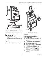
Changing Hub Inserts.
Change hub insert sizes by removing retaining ring and lifting
hub insert from actuator. Put new insert in place and replace
retaining ring. See Fig. 4. Be careful when removing the
retaining ring that secures the output hub to actuator housing.
Use a flathead screwdriver to pry ring loose.


