background image

ML6425, ML7425 SPRING RETURN ELECTRIC LINEAR VALVE ACTUATORS

63-2516—04

6

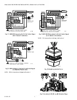
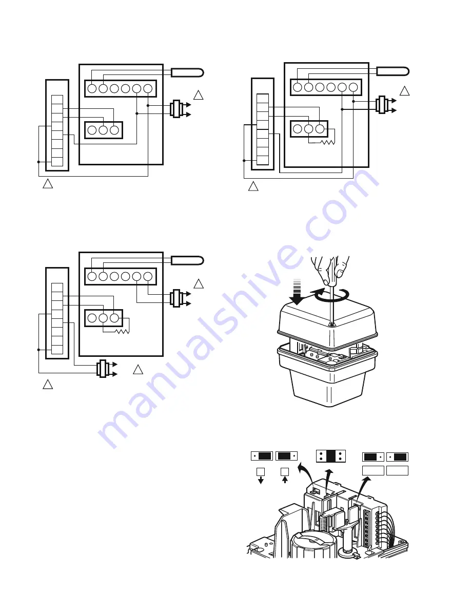
Fig. 11. ML7425 Wiring using 2 to 10 Vdc Control Signal 

and a Common Transformer.

Fig. 12. ML7425 Wiring using 4 to 20 mA Control Signal 

and Separate Transformers.

NOTE: 500 ohm resistor not shipped with product.

Fig. 13. ML7425 Wiring using 4 to 20 mA Control Signal 

and a Common Transformer.

NOTE: 500 ohm resistor not shipped with product.

Fig. 14. Replacing Actuator Cover.

Fig. 15. Location of W1, W2, and W3 Selector Plugs.

L1 
(HOT)
L2

1

1

WIRING
STRIP

F

+

T2

T1

O1

O2

TS

1

1

2

2

3

3

4

5

6

ML7425

T775

(WITH 2-10 VDC OUTPUT)

SINGLE
TRANSFORMER
40 VA 24 VAC

POWER SUPPLY.  PROVIDE DISCONNECT MEANS 
AND OVERLOAD PROTECTION AS REQUIRED.

M7895

SENSOR

L1 
(HOT)
L2

1

1

WIRING
STRIP

F

+

T2

T1

O1

O2

TS

1

1

2

2

3

3

4

5

6

L1 
(HOT)
L2

1

ML7425

T775

(WITH 4-20 MA OUTPUT)

DUAL
TRANSFORMERS

POWER SUPPLY.  PROVIDE DISCONNECT MEANS AND 
OVERLOAD PROTECTION AS REQUIRED.

M7896

500 OHM
RESISTOR

SENSOR

L1 
(HOT)
L2

1

1

WIRING
STRIP

F

+

T2

T1

O1

O2

TS

1

1

2

2

3

3

4

5

6

ML7425

SENSOR

T775 

(WITH 4-20 MA OUTPUT)

SINGLE
TRANSFORMER
40 VA 24 VAC

POWER SUPPLY.  PROVIDE DISCONNECT MEANS 
AND OVERLOAD PROTECTION AS REQUIRED.

M7897

500 OHM
RESISTOR

M6628

M6631

0 ... 10V

2 ... 10V

W2

10V

0%

10V

W3

W1

100%

50%

Summary of Contents for ML6425 Series

Page 1: ...l valves in heating ventilating and air conditioning HVAC applications An internal selector plug can be used to reverse the direction of action FEATURES ML6425 and ML7425 Accurate valve positioning Quick and easy installation No separate linkage required On power failure ML6425A and ML7425A drive valve stem down ML6425B and ML7425B draw valve stem up Conduit connector is standard No adjustments re...

Page 2: ... Vac Signal Source Output Resistance 1 kOhm maximum Signal Load 1 mA maximum Signal Inputs Supply Voltage Between Terminals ML6425 B and 24 Vac Drive valve stem down W and 24 Vac Draw valve stem up ML7425 0 to 10 Vdc or 2 to 10 Vdc Stem Force 135 lbf 600 N Actuator Stroke 3 4 in 19 mm Actuator Run Time at 60 Hz 90 seconds Spring Return Time 12 seconds Temperature Ranges Ambient 14 to 122 F 10 to 5...

Page 3: ...e the actuator to the valve by turning each U bolt nut clockwise To assure even pressure on the collar first tighten the nuts finger tight and then alternate turning each U bolt nut until both are snug 3 Push aside the stem button retaining clip and hold Refer to Fig 3 4 Lift valve stem until the head of the valve stem button is inside the large slot of the stem button retaining clip on the actuat...

Page 4: ...r must correspond with the power supply and actuator characteristics Refer to Figures 6 through 13 for connection information and typical wiring hookups 1 Feed power and control wires through the conduit connector located on the bottom of the actuator case See Fig 6 CAUTION Equipment Damage Hazard Conduit connection or removal can break an unsupported connector When removing or attaching conduit u...

Page 5: ...F THE POTENTIOMETER ACCESSORY KITS MOTOR OPEN SIGNAL DRAWS VALVE STEM UPWARDS MOTOR CLOSE SIGNAL DRIVES VALVE STEM DOWNWARDS 1 2 3 4 T6984 FLOATING CONTROLLER M25446 MOTOR OPEN MOTOR CLOSE COMMON 24 Vac POWER SUPPLY PROVIDE DISCONNECT MEANS AND OVERLOAD PROTECTION AS REQUIRED TS MUST BE POWERED OR THE ACTUATOR WILL SPRING RETURN ML7425A B WIRING STRIP F Ð T2 T1 O1 O2 TS 1 2 2 10 Vdc OUTPUT T7984 2...

Page 6: ...G STRIP F T2 T1 O1 O2 TS 1 1 2 2 3 3 4 5 6 ML7425 T775 WITH 2 10 VDC OUTPUT SINGLE TRANSFORMER 40 VA 24 VAC POWER SUPPLY PROVIDE DISCONNECT MEANS AND OVERLOAD PROTECTION AS REQUIRED M7895 SENSOR L1 HOT L2 1 1 WIRING STRIP F T2 T1 O1 O2 TS 1 1 2 2 3 3 4 5 6 L1 HOT L2 1 ML7425 T775 WITH 4 20 MA OUTPUT DUAL TRANSFORMERS POWER SUPPLY PROVIDE DISCONNECT MEANS AND OVERLOAD PROTECTION AS REQUIRED M7896 5...

Page 7: ... back side of the printed circuit board Refer to Fig 15 for location of the selector plugs Signal Input Failure Using selector plug W1 the actuator can be set to run to one of three positions in event of a signal failure 0 Actuator position corresponds with 0 or 2 Vdc signal 50 Actuator stem in mid position 100 Actuator position according to 10 Vdc signal NOTE W1 is factory set at the mid position...

Page 8: ...ower to the appropriate leadwires to move the valve 4 If the actuator does not move make sure the actuator is properly installed wired 5 If the actuator installation and wiring are both correct and the actuator does not run replace the actuator Controller Checkout 1 Adjust the setpoint of the controller to call for opening the valve Observe the actuator 2 If the valve is closed it should begin to ...

Reviews: