background image

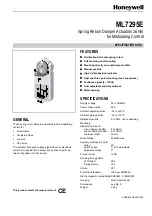
ML7295E DAMPER ACTUATORS

3

EN0B-099GE02 R1298

INSTALLATION

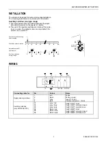
The actuator is designed for dual point mounting/installation.
The mounting instructions are enclosed with the actuator.

Auxiliary switches (see type range

)

1) The figure below shows the relation between the adjust-

able switching point and the angular of rotation.

2) The axis of the auxiliary switches are rotating if the actua-

tor is in motion. The printed scales are only usable if the
actuator is in position 0

°

.

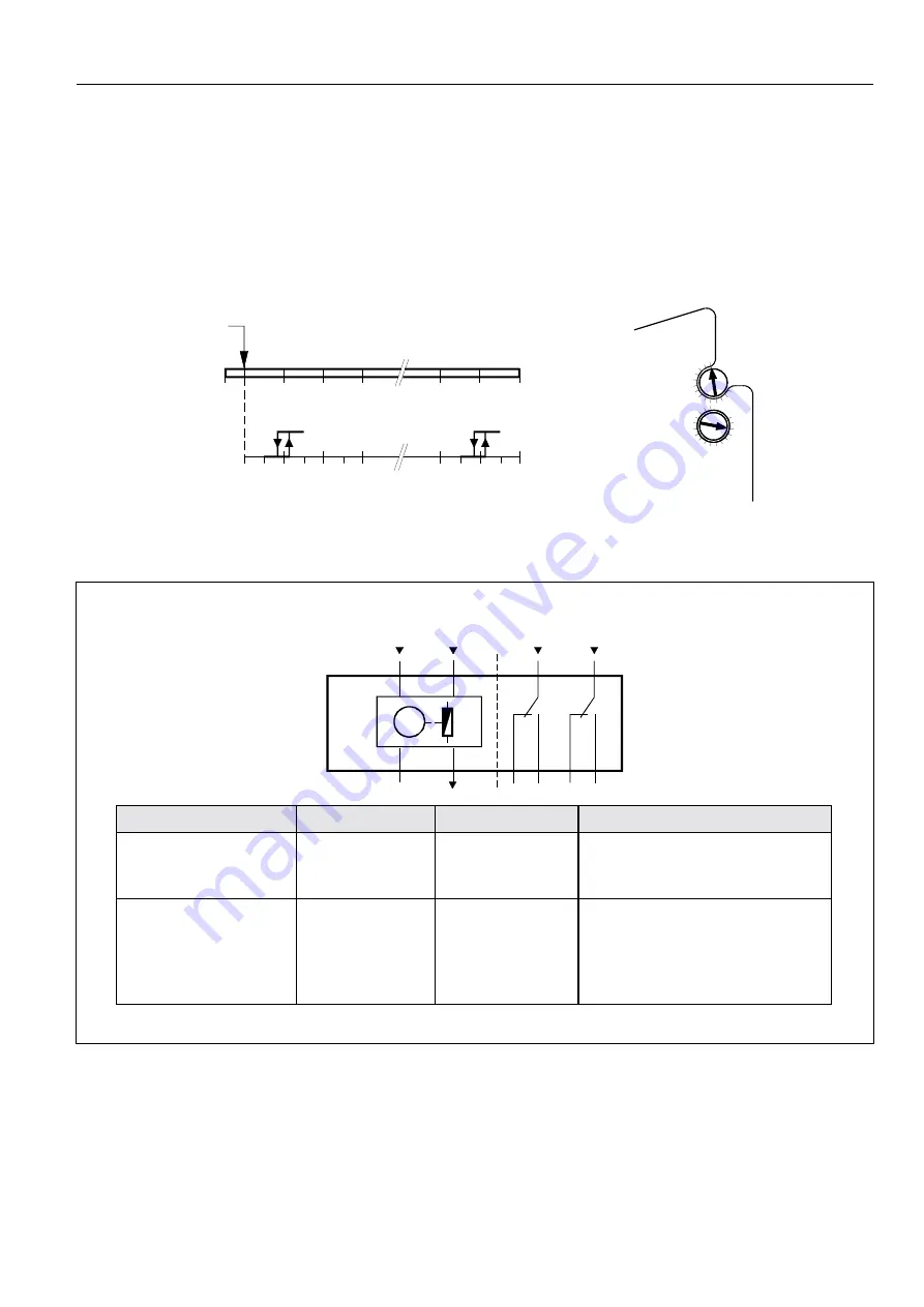
WIRING

M

A

100%

0%

(L

)

(Y

)

(N

)

(U

)

2

4

S2 S3

S5 S6

1

3

S1

S4

B

A

B

-5°

10°

20°

30°

70°

80°

90°

10°

20°

30°

70°

80°

90°

4637D03

Position for self centering
shaft coupling

Printed angular of rotation

Adjustable steps 5

°,

Hysteresis 2

°

Auxiliary switches 

setting range


80

70

60

50

B

90

Aux Switch
Adjustment

20

30

40

10

20

40

A

70

46

37

Z

0

7

Connecting cable for

No.

Colour

Name

Supply and signal lines

1
2
3
4

red
black
gray
pink

24Vac
24Vac ground
Input 0...10Vdc
Position indicator 2...10Vdc

Auxiliary switches
(only ML7295E1015)

S1
S2
S3
S4
S5
S6

grey / red
grey / blue
grey / pink
black / red
black / blue
black / pink

Switch A(12

°

) input

Switch A(12

°

) normally closed

Switch A(12

°

) normally open

Switch B(82

°

) input

Switch B(82

°

) normally closed

Switch B(82

°

) normally open

Summary of Contents for ML7295E

Page 1: ...stable auxiliary switches Metal housing SPECIFICATIONS Supply voltage 24V 50 60Hz Power consumption 9VA Ambient operating limits 32 to 55 C Ambient storage limits 32 to 70 C Relative Humidity 5 to 95 non condensing Mounting standard hub insert round damper shafts 8 to 26mm square damper shafts 6 to 18mm minimum length 20mm Noise Rating 45dB A max Auxiliary switches A and B rating 2A switch points ...

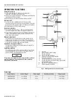
Page 2: ...e of the equipment and locked by a screwdriver To unlock just by screwdriver or connect the actuator with the power supply Limitation of angular rotation The angular of rotation can be set between 0 and 90 in adjustment steps of 5 Auxiliary switches The switching points of the auxiliary switches A and B can be set independent of each other in the range of the an gular of rotation in adjustment ste...

Page 3: ... 4 S2 S3 S5 S6 1 3 S1 S4 B A B 5 0 10 20 30 70 80 90 0 10 20 30 70 80 90 4637D03 Position for self centering shaft coupling Printed angular of rotation Adjustable steps 5 Hysteresis 2 Auxiliary switches setting range 80 70 60 50 B 90 Aux Switch Adjustment 20 30 40 10 20 40 A 70 4637Z07 Connecting cable for No Colour Name Supply and signal lines 1 2 3 4 red black gray pink 24Vac 24Vac ground Input ...

Page 4: ...MPER ACTUATORS EN0B 099GE02 R1298 4 ACCESSORIES Description Order Number Rotary linear adapter frame mounting kit 210033 Rotary linear adapter foot mounting kit 210034 Rotary linear set for duct mounting ASK71 4 ...

Page 5: ...ML7295E DAMPER ACTUATORS 5 EN0B 099GE02 R1298 DIMENSIONS Fig 2 Dimensions ML7295E in mm inch ...

Page 6: ...eme GmbH Helping You Control Your World Honeywellstr 2 6 D 63477 Maintal Tel 0 61 81 401 1 Fax 0 61 81 401 400 Subject to change without notice Printed in Germany EN0B 099GE02 R1298 DIN EN ISO 9001 Manufacturing location is certified according to ...

Reviews: