background image

ML7984B 

WIRING 

24 Vac 

2

ML7984B 

L1 

L2 

T5 

T6

3

SIGNAL

 SOURCE 

2-10 Vdc 

PWM 

OR 

+

T6 

28 Vdc 

-

T5 

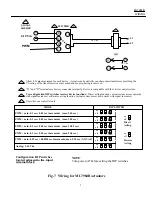
Allow 0.5 amps maximum for each device.  Actuators and controller can share same transformer providing the 
VA rating of the transformer is not exceeded and proper phasing is observed. 

"T5" and "W" terminals are factory connected internally. Device is compatible with the 3-wire control system. 

Use configuration DIP switches to select device functions:  Direct acting function ( actuator stem moves upwards 
with signal increases ) or Reverse acting function ( actuator stem moves downwards with signal increases ). 

Use either one controller only 

on 

off 

on 

off 

Reverse 

Acting 

on 

off 

Direct 

Acting 

MODE 

DIP SWITCH 

PWM:  min. 0.1 sec + 0.01 sec increments  (max. 2.65 sec ) 

PWM:  min. 0.1 sec + 0.02 sec increments  (max. 5.20 sec ) 

PWM:  min. 0.1 sec + 0.05 sec increments  (max. 12.85 sec ) 

PWM:  min. 0.1 sec + 0.10 sec increments  (max. 25.6 sec ) 

PWM:  min. 0.59 sec + 0.00918 sec increments (max. 2.93 sec ) NOVAR 

Analog: 2-10 Vdc 

on 

off 

on 

off 

on 

off 

on 

off 

on 

off 

Configuration  DIP switches 

NOTE:

located adjacent to the  input 

Turn power off before setting the DIP switches.

terminal block 

Fig. 7  Wiring  for ML7984B actuators 

Summary of Contents for ML7984B

Page 1: ...rect Reverse action One device for either Vac or Vdc power supply application Compatible with 3 wire system one common wire for both signal power inputs For 1 2 to 3 V5011 V5013F G valves Self contained motorized valve linkage Linkage self adjusts to valve stroke of up to 19 mm 3 4 Multipoise mounting Strong valve seat closing force 710 Newton 160 lbs Compact size for easy installation in confined...

Page 2: ...iming Approx 63 seconds for 3 4 stroke Closing Force 710N 160 lbs Nominal Rating applies to both directions Performance Specifications Life Expectancy at rated load and power conditions 50 000 full stroke cycles plus 1 000 000 repositions at 10 stem travel or 10 years whichever occurs first Note rapid repositioning will result in reduced service life of the actuator Ordering Information When purch...

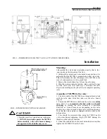
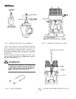
Page 3: ...sition indicator plastic disk or rubber O ring over the valve stem See inset Fig 3 Indicator will self align to the marking on the yoke after one complete operating cycle Assembly of ML7984 to the valve 1 The drive shaft of the ML7984 has a threaded hole to link with the valve stem Slide the yoke over the valve bonnet Fig 4 2 Thread the ML7984 drive shaft onto the valve stem all the way until it i...

Page 4: ...re included in the plastic bag into the top of the shaft slot hex side up 6 With a 5 mm 3 16 Slotted screwdriver or 1 8 x 6 Allen wrench included in the plastic bag tighten the set screw to lock valve stem in place Fig 6 WARNING For proper valve operation valve stem must be threaded into the actuator all the way with no threads showing and locked in place with the set screw provided FIG 4 ASSEMBLY...

Page 5: ...with signal increases or Reverse acting function actuator stem moves downwards with signal increases Use either one controller only 1 2 3 on off 4 on off Reverse Acting 4 on off Direct Acting MODE DIP SWITCH PWM min 0 1 sec 0 01 sec increments max 2 65 sec PWM min 0 1 sec 0 02 sec increments max 5 20 sec PWM min 0 1 sec 0 05 sec increments max 12 85 sec PWM min 0 1 sec 0 10 sec increments max 25 6...

Page 6: ...wiring diagram for details Turn power off before setting the DIP switches 2 There is a short delay in actuator response upon every signal change It is to screen any unwanted incoming signals 3 For proper operation voltage on the T5 T6 must not be less than 22Vac or 24Vdc during running or force generating stages CAUTION 1 Disconnect power supply before beginning installation to prevent electrical ...

Reviews: