background image

ML7999A UNIVERSAL PARALLEL-POSITIONING ACTUATOR

3

65-0239—2

Fig. 1. ML7999 dimensions in in. (mm).

Fig. 2. V5197A Firing Rate Gas Valve, with 

mounting bracket (included) and ML7999 Actuator 

(not supplied), dimensions in in. (mm).

INSTALLATION

When Installing this Product...

1.

Read these instructions carefully. Failure to follow them 

could damage the product or cause a hazardous 

condition.

2.

Check the ratings given in the instructions and on the 

product to make sure the product is suitable for your 

application.

3.

Installer must be a trained, experienced service 

technician.

4.

After installation is complete, check out product 

operation as provided in these instructions.

WARNING

Fire or Explosion Hazard.

Can cause property damage, severe personal 

injury, or death.

Tighten the hub setscrews to a torque of 

60 lb-in. (7 N•m).

WARNING

Electrical Shock Hazard.

Can Cause serious injury or death. 

Disconnect power supply before installation.

Location

CAUTION

Actuator Damage Hazard.

Deteriorating vapors and acid fumes can damage 

the actuator metal parts.

Install actuator in areas free of acid fumes and other 

deteriorating vapors.

Mounting ML7999 Actuator

The actuator mounts on a 1/2 in. round or square shaft. For 

shafts smaller than 1/2 in, self-centering adapters are 

available for 5/16 in. and 3/8 in. shafts. For shafts larger than 

1/2 in., adapters are available for 5/8 in., 3/4 in., and 9/16 in.

CAUTION

Equipment Damage Hazard.

Lateral forces on actuator hub will damage 

actuator.

Ensure actuator is mounted with shaft centered in 

actuator hub.

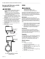
1.

Place the actuator over the shaft, see Fig. 3.

2.

Position and seat the actuator.

3.

Rotate the shaft to match the actuator position.

4.

Install the mounting bracket accessory (not included), 

if needed. See Fig. 4.

5.

Partially tighten hub setscrews to ensure actuator 

seats firmly against mounting bracket with shaft 

centered in hub.

6.

Tighten the anti-rotation bolt to the torque 

recommendation for the selected bolt/nut.

7.

Tighten the hub setscrews against the shaft to a torque 

of 60 lb-in.

4 (102)

7/8 (22)

1-7/8 (47)

1/2

(13)

3-1/2 (89)

1-5/8

(41)

5-1/2
(140)

6

(153)

M16466

1/4-28

unF

10-5/16

(277)

4-27/32 (123)

6-7/16 (165)

2-1/2 (64)

7-1/8
(181)

3-25/32

(96)

M17528

Summary of Contents for ML7999A

Page 1: ...FEATURES Universal power supply input Password protected with an eight digit hexadecimal identification signal 100 lb in 11 3 Nm torque Includes integral position feedback potentiometer Separate wiring compartment between line voltage power wiring and low voltage control Direct coupling shaft interface mounting Couples directly to a 1 2 in 13 mm shaft with no additional parts required Couples dire...

Page 2: ...differential between DR1 DR2 Drive Counterclockwise Maximum 4 25 Vdc differential between DR1 DR2 NOTE Actuator does not respond until the 8 digit ID signal from the R7999 is passed via DR1 DR2 Actuator Stroke 95 nominal 3 mechanically limited Output Hub Position Accuracy 0 1 Torque Ratings at Rated Voltages Lift and Hold Minimum 100 lb in 11 3 Nm Breakaway Minimum 100 lb in 11 3 Nm Stall Minimum ...

Page 3: ... and acid fumes can damage the actuator metal parts Install actuator in areas free of acid fumes and other deteriorating vapors Mounting ML7999 Actuator The actuator mounts on a 1 2 in round or square shaft For shafts smaller than 1 2 in self centering adapters are available for 5 16 in and 3 8 in shafts For shafts larger than 1 2 in adapters are available for 5 8 in 3 4 in and 9 16 in CAUTION Equ...

Page 4: ... Ground Earth ground is required for proper operation of the ControLinks system Earth ground provides a connection between the subbase and the control panel of the equipment The earth ground must be capable of conducting enough current to blow the fuse or breaker in the event of an internal short 1 Use wide straps or brackets to provide minimum length maximum surface area ground conductors If a le...

Page 5: ...r is low check the power supply 3 Ensure actuator stroke matches stroke of damper or valve a Remove the cover b Press the button labeled CW The actuator should drive the device clockwise c Press the button labeled CCW The actuator should drive the device counterclockwise 4 If the actuator operates properly check the controller for proper output signals 5 If the actuator does not drive remove power...

Page 6: ... does not drive replace the actuator 9 If the actuator and device shaft turn freely remount the actuator to the device according to instructions in the Installation section Make sure the actuator does not bind and that the actuator and device are both at the same clockwise or counterclockwise end stop when assembled Hook up the wires and repeat the Checkout procedures Troubleshoot if necessary ...

Page 7: ...7 65 0239 2 ...

Page 8: ...well Europe S A Honeywell Latin American Honeywell International Inc Honeywell Limited Honeywell Limitée Control Products 3 Avenue du Bourget Region 1985 Douglas Drive North 35 Dynamic Drive Honeywell Building 1140 Brussels 480 Sawgrass Corporate Parkway Golden Valley MN 55422 Scarborough Ontario 17 Changi Business Park Central 1 Belgium Suite 200 M1V 4Z9 Singapore 486073 Sunrise FL 33325 ...

Reviews: