background image

PRODUCT DATA

32-00079EF-01

ML7999C Universal 
Parallel-Positioning Actuator

APPLICATION

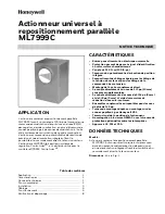
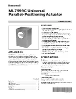
ML7999C Universal Parallel-Positioning Actuator 
provides 100 lb-in. torque, pulse-width-modulating 
(PWM) control of combustion air dampers, butterfly gas 
valves, oil modulation valves, and flue gas recirculation 
systems. The actuator includes a precision feedback 
potentiometer and integral power supply capable of direct 
line voltage connection. The ML7999C Actuator is part of 
the ControLinks™ Control System, and must be used with 
the R7999C ControLinks™ Controller.

FEATURES

• Universal power supply input.
• Password protected with an eight-digit hexadecimal 

identification signal.

• 100 lb-in. (11.3 Nm) torque.
• Includes integral position feedback potentiometer.
• Separate wiring compartment between line voltage 

power wiring and low voltage control.

• Direct coupling shaft interface mounting.
• Couples directly to a 1/2 in. (13 mm) shaft with no 

additional parts required.

• Couples directly to 5/16 in. (8 mm) and 3/8 in. (9 

mm) shafts using available self-centering shaft 
reduction accessories.

• Shaft coupler assembly available for shafts larger 

than 1/2 in.

• Bracket Accessory Kit available for mounting to 

Honeywell V51 Butterfly Gas Valves.

• Visual indication of actuator position.
• NEMA 3 rating with optional weatherproof kit.
• UL, FM, CSA approved.

SPECIFICATIONS

Model:

ML7999C Universal Parallel-Positioning Actuator. 

Medium torque electronic actuator with a precision 
feedback potentiometer and integral power supply 
capable of direct line voltage connection.

Dimensions: 

See Fig. 1.

Electrical Ratings:

Power Input: 100 to 240 Vac +10% -15%, 50/60 Hz.
Maximum Power Consumption: 15 VA.

IMPORTANT

Device must be hardwired.

Temperature Range:

Ambient: -40°F to +140°F (-40°C to +60°C).
Storage: -40°F to +150°F (-40°C to +66°C).

Humidity Range (at 95°F [35°C]): 

5 to 95 percent relative 

humidity, noncondensing.

Contents

Application .....................................................................................

1

Features ..........................................................................................
1

Specifications ...............................................................................

1

Ordering Information  ................................................................

2

Installation .....................................................................................
3

Wiring ...............................................................................................

4

Operation .......................................................................................
5

Checkout And Troubleshooting .............................................

8

Summary of Contents for ML7999C

Page 1: ...1 2 in 13 mm shaft with no additional parts required Couples directly to 5 16 in 8 mm and 3 8 in 9 mm shafts using available self centering shaft reduction accessories Shaft coupler assembly available for shafts larger than 1 2 in Bracket Accessory Kit available for mounting to Honeywell V51 Butterfly Gas Valves Visual indication of actuator position NEMA 3 rating with optional weatherproof kit UL...

Page 2: ... 100 lb in 11 3 Nm Breakaway Minimum 100 lb in 11 3 Nm Stall Minimum 100 lb in 11 3 Nm Stall Maximum 150 lb in 17 Nm Actuator Design Life at 100 lb in Full Stroke Cycles 100 000 minimum Repositions 2 000 000 minimum Feedback Potentiometer Total Resistance 5000 ohms 10 Actuator Timing 90 Travel Standard 24 to 30 seconds Derated Cold Start Timing from 40 F to 20 F 40 C to 29 C 150 seconds maximum No...

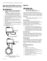
Page 3: ...amage actuator Do not locate actuator where ambient temperatures will exceed the limits listed in the Specifications section CAUTION Equipment Damage Hazard Excessive vibration will damage actuator Do not locate actuator where vibration will exceed the limits listed in the Specifications section Mounting ML7999C Actuator The actuator mounts on a 1 2 in round or square shaft For shafts smaller than...

Page 4: ...in separate conduit to avoid signal interference Earth Ground Earth ground is required for proper operation of the ControLinks system Earth ground provides a connection between the subbase and the control panel of the equipment The earth ground must be capable of conducting enough current to blow the fuse or breaker in the event of an internal short 1 Use wide straps or brackets to provide minimum...

Page 5: ... buttons are labeled CW and CCW To use them the only required wiring connections are L1 L2 and GND However after the device is installed and wired to the R7999 do not use these buttons for anything but troubleshooting Password Protection ID Signal Before using the actuator the ID signal must be set See the software interface instructions for details After this signal is set the R7999C sends the si...

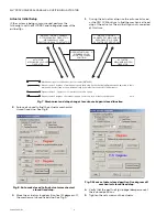
Page 6: ...ve actuator closed position five degrees off mechanical closed fixed stop 4 Verify that the gas fuel fgr linkage dampers are at their closed positions 5 Tighten the set screws on the actuator OPEN ACTUATORS 2 5 DEGREES LOCK ACTUATOR CLOSED POSITION ACTUATOR MECHANICAL CLOSED FIXED STOP Mechanical open closed fixed stops of actuator ML7999C Move actuator 5 degrees of mechanical closed fixed stop Ve...

Page 7: ...10 Move actuator linkage damper 2 5 degrees off mechanical closed fixed stop 7 Auto seek open to actuator mechanical open fixed stop See Fig 11 Fig 11 Auto seek open to actuator mechanical open fixed stop 8 Move the actuator five 5 degrees off the mechanical open stop See Fig 12 Fig 12 Move actuator five degrees off the mechanical open stop 9 Lock actuator open position See Fig 13 Fig 13 Lock actu...

Page 8: ...ld drive the device clockwise c Press the button labeled CCW The actuator should drive the device counterclockwise 4 If the actuator operates properly check the control ler for proper output signals 5 If the actuator does not drive remove power discon nect the actuator hub and try to turn the shaft clockwise and counterclockwise If the shaft turns freely throughout the 90 degree stroke and the act...

Page 9: ...intégrée Compartiment de câblage séparé pour le câblage de la tension de secteur et pour le câblage de la commande à basse tension Montage de l axe à accouplement direct Se couple directement à un axe de 1 2 po 13 mm sans pièce supplémentaire Se couple directement à des axes de 5 16 po 8 mm et de 3 8 po 9 mm à l aide d accessoires de réduction d axe auto centreurs Ensembles coupleur d axe disponib...

Page 10: ...se de l actionneur 95 nominal 3 limité mécaniquement Précision de la position du moyeu de sortie 0 1 Couples nominaux aux tensions nominales Couple de levage et de maintien minimal 11 3 N m 100 lb po Couple de manœuvre minimal 11 3 N m 100 lb po Couple de maintien minimal 11 3 N m 100 lb po Couple de maintien maximal 17 N m 150 lb po Durée de vie de l actionneur à 100 lb po Courses complètes 100 0...

Page 11: ...ager les pièces métalliques de l actionneur Installez l actionneur à un endroit non exposé aux vapeurs d acides ou à d autres vapeurs destructrices MISE EN GARDE Risque d endommagement de l équipement Les températures extrêmes endommagent l actionneur Ne pas installer l actionneur à un endroit où les températures ambiantes dépassent les limites prescrites dans la section Spécifications MISE EN GAR...

Page 12: ... support de montage à l aide des vis fournies 4 Câblez l actionneur ML7999C conformément aux instructions de la section Câblage 5 Rétablissez l alimentation du système Fig 3 Montage de l actionneur ML7999C Fig 4 Montage de l actionneur ML7999C avec le support de montage CÂBLAGE AVERTISSEMENT Danger de décharge électrique Peut causer des blessures graves ou le décès Débranchez l alimentation avant ...

Page 13: ...vannes de modulation à l huile et de systèmes de recirculation des gaz de combustion qui nécessitent un couple maximum de 100 lb po Un contrôleur R7999C commande l actionneur ML7999C L actionneur est muni d un indicateur de position qui indique la position de l axe L indicateur se déplace avec l axe pour fournir une représentation angulaire de la position de ce dernier IMPORTANT Une fois que le co...

Page 14: ...ille les signaux de commande ou de mise hors ligne Allumée fixe Non Non Panne de l actionneur Réinitialiser l actionneur aux valeurs d usine OUVREZ LES ACTIONNEURS DE 2 À 5 DEGRÉS VERROUILLEZ LA POSITION FERMÉE DE L ACTIONNEUR BUTÉE FIXE DE FERMETURE MÉCANIQUE DE L ACTIONNEUR Butées fixes d ouverture de fermeture mécanique de l actionneur ML7999C Déplacez l actionneur de 5 degrés par rapport à la ...

Page 15: ...mbustion sont en position fermée 5 Serrez les vis de réglage sur l actionneur 6 Déplacez la tringlerie et le registre de l actionneur de 2 à 5 degrés par rapport à la butée de fermeture mécanique de la tringlerie et du registre Verrouillez la position fermée de l actionneur Voir la Fig 10 Fig 10 Déplacez la tringlerie et le registre de l actionneur de 2 à 5 degrés par rapport à la butée de fermetu...

Page 16: ... correspond à la course du registre ou du régulateur a Retirez le couvercle b Appuyez sur le bouton étiqueté CW L actionneur devrait entraîner l appareil dans le sens horaire c Appuyez sur le bouton étiqueté CCW L actionneur devrait entraîner l appareil dans le sens antihoraire 4 Si l actionneur fonctionne correctement vérifiez que les signaux de sortie du contrôleur sont adéquats 5 Si l actionneu...

Reviews: