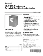
ML7999C UNIVERSAL PARALLEL-POSITIONING ACTUATOR
5
32-00079EF—01
Fig. 5. Opening ML7999C low-voltage wiring
compartment.
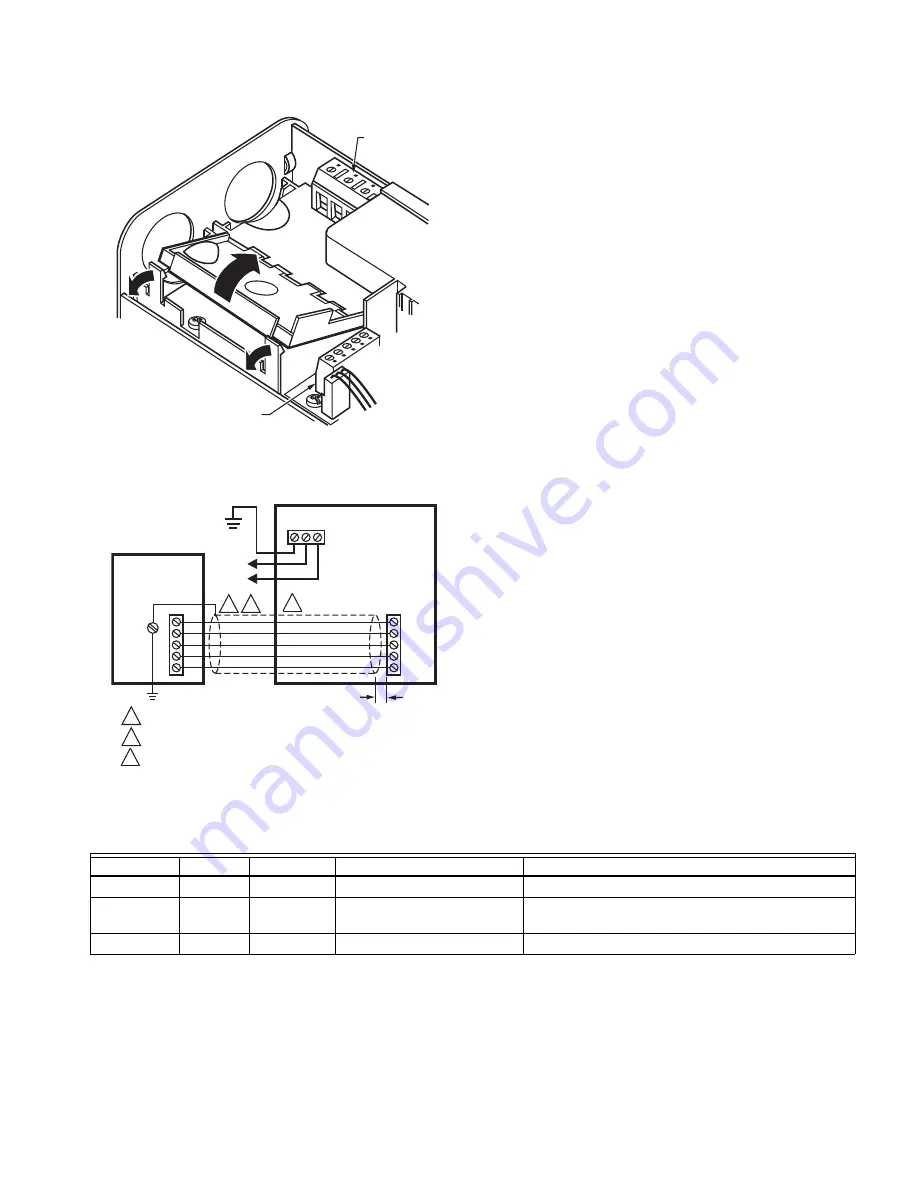
Fig. 6. Typical ML7999C wiring.
OPERATION
ML7999C Universal Parallel-Positioning Actuator is
designed to operate combustion air dampers, butterfly gas
valves, oil modulation valves, and flue gas recirculation
systems requiring up to 100 lb-in. torque. An R7999C
controller operates the ML7999C.
The actuator has a position indicator that shows shaft
position. As the indicator moves with the shaft, it provides
an angular representation of the shaft position.
IMPORTANT
When the cover is removed and replaced, the
position indicator will not operate until manually
rotated clockwise to engage it. An audible click
indicates the position indicator is engaged.
NOTE:
While installing the actuator, the hub can be
manually driven using the push buttons located
under the cover. The buttons are labeled CW and
CCW. To use them, the only required wiring
connections are L1, L2, and GND. However, after
the device is installed and wired to the R7999, do
not use these buttons for anything but
troubleshooting.
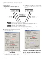
Password Protection (ID Signal)
Before using the actuator, the ID signal must be set. See
the software interface instructions for details. After this
signal is set, the R7999C sends the signal to operate the
actuator. Until the appropriate ID signal is sent, the
actuator is offline and responds only to its own ID signal.
(See Table 1.)
.
M16470
LINE VOLTAGE
WIRING
LOW
VOLTAGE
WIRING
GND
L2 L1
DR1
DR2
CW
S
CCW
L2
L1
ML7999
R7999
M16469A
1/2 IN. MAXIMUM
TERMINATE WIRE SHIELD AT THE CONTROLLER (R7999).
SEE FIGURE 5 FOR ACTUATOR WIRING.
RUN LOW/LINE VOLTAGE IN SEPARATE CONDUIT.
1
2
1
2
G
3
3
Table 1. On-Board LED Indications
LED
Online
Configured
Meaning
Notes
Fast Blink
No
Yes
Awaiting ID signal.
Responds only to ID signal.
Slow Blink
Yes
Yes
ID signal recognized.
Monitors signals for operation or offline
commands.
Steady On
No
No
Actuator has failed.
Return actuator to factory.

