background image

SERIES 71, 72, AND 76 MODUTROL IV™ MOTORS

63-2640—07

8

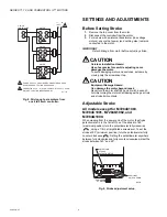
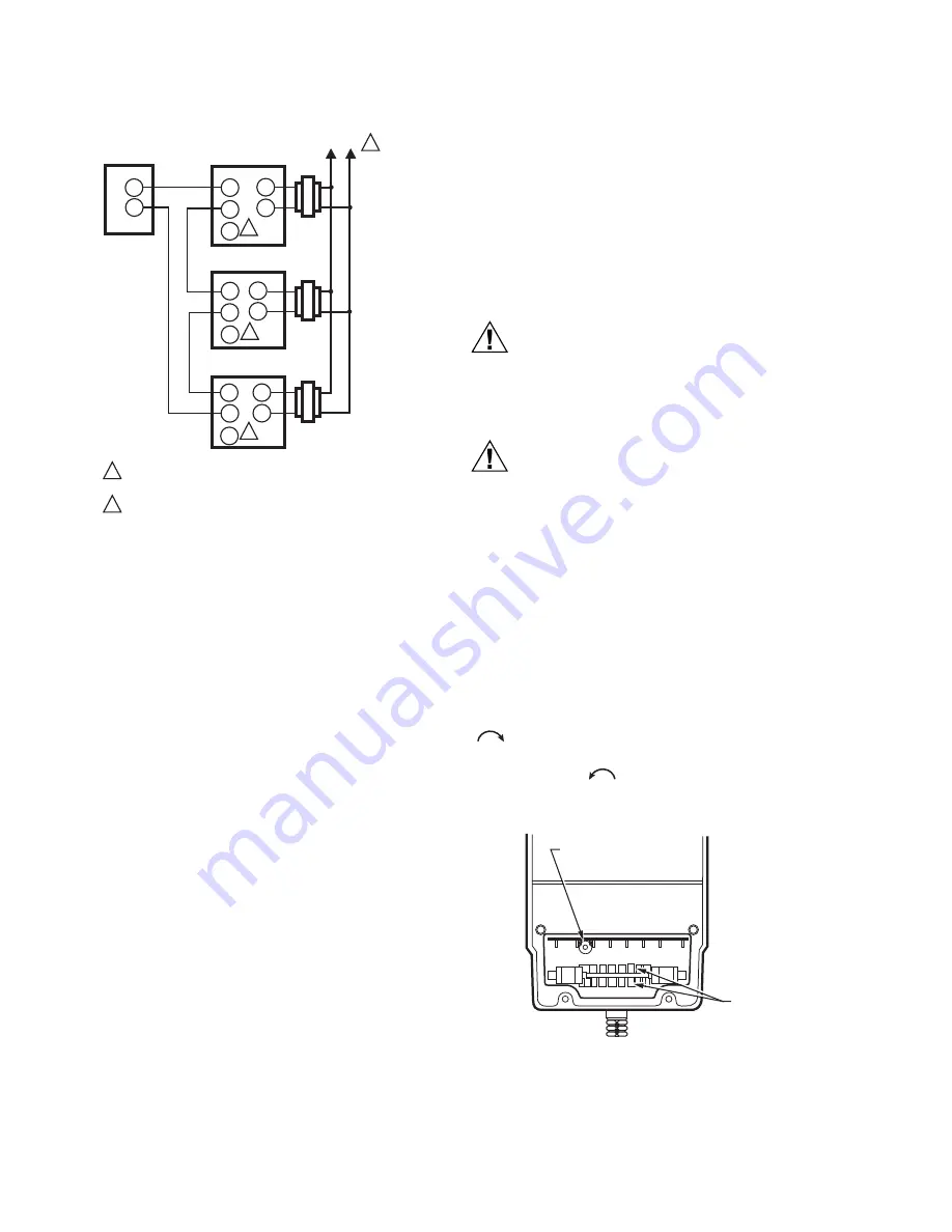
Fig. 8. Driving up to six motors from 

one 4 to 20 mA controller.

SETTINGS AND ADJUSTMENTS

Before Setting Stroke

1.

Remove the top cover from the motor.

2.

Disconnect the controller from the motor.

3.

For models with an internal transformer (line voltage 

motors), ensure that power (and nothing else) remains 

connected to the motor.

IMPORTANT

Detach linkage from motor before adjusting stroke.

CAUTION

Careless Installation Hazard.

Use of excessive force while adjusting cams 

damages the motor.

To avoid damaging motor end switches, set cams by 

moving only the screwdriver top.

CAUTION

Equipment Damage Hazard.

Can damage the motor beyond repair.

Never turn the motor shaft by hand or with a wrench.

Forcibly turning the motor shaft damages the gear train 

and stroke limit contacts.

Adjustable Stroke

All models except for M7284C1083, 
M7284C1091, M7284Q1082, and 
M7284Q1090.

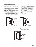
When viewing from the power end of the motor, the stroke 

potentiometer is to the far left. To set the stroke to 160° 

(maximum position) turn the potentiometer fully clockwise 

, using a 1/8 in. straight-blade screwdriver. To set the 

stroke at 90° (minimum position) turn the potentiometer fully 
counter-clockwise 

. Setting the potentiometer anywhere 

between fully clockwise and fully counter-clockwise will set the 

stroke between 160° and 90°.

Fig. 9. Stroke adjustment setup

4-20 mA

CONTROLLER

L1

(HOT)

L2

POWER SUPPLY.  PROVIDE DISCONNECT MEANS AND

OVERLOAD PROTECTION AS REQURED.

CONNECTING F TO – WILL DRIVE MOTOR TO FULLY OPEN.

MOTORS FUNCTION INDEPENDENTLY.

1

M31109

1

 MOTOR

 MOTOR

+

-

 MOTOR

2

F

T1

T2

2

F

T1

T2

2

F

T1

T2

2

+

-

+

+

-

-

M13699

POWER END

OF MOTOR

AUXILIARY 

SWITCH CAMS 

ADJUSTABLE

STROKE 

POTENTIOMETER

Summary of Contents for Modutrol IV 71 Series

Page 1: ...crew terminal adapter is available Adapter bracket for matching shaft height of older motors is available Most motors have field adjustable stroke 90 to 160 Die cast aluminum housing Integral auxiliary switches are available factory mounted or can be field added Nominal timing standard of 30 seconds 90 stroke and 60 seconds 160 stroke Other timings available Spring return motors can operate valve ...

Page 2: ...ny electronic controller that provides a stable noise free proportional current output as specified in Electrical Ratings Input Range below Electrical Ratings Power Consumption See Table 1 Input Range Current Nonadjustable 4 to 20 mA nominal 25 mA maximum Current Adjustable 4 to 20 mA adjustable 50 mA maximum Zero Null Motor Closed 0 0 to 18 mA Span 1 8 to 20 mA Voltage Nonadjustable 2 to 10 Vdc I...

Page 3: ...ual ended shaft Normally Closed Spring Return 4 Non Spring Return 5 Normally Closed Spring Return A 0 Auxiliary Switches Adjustable Stroke Normally Closed B 1 Auxiliary Switch C 2 Auxiliary Switches D 0 Auxiliary Switch Qa 2 Auxiliary Switches M 72 8 4 A XXXX See Tradeline Catalog for Complete Model Number FULLY OPEN 90 DEGREE STROKE 160 DEGREE STROKE M31079 VERTICAL REFERENCE FULLY CLOSED 160 10 ...

Page 4: ...Y END POWER END ADAPTER BRACKET 2 9 16 66 5 3 8 137 6 7 16 164 9 16 15 3 4 19 TOP VIEW OF BRACKET TOP VIEW 4 5 8 116 4 1 4 107 2 5 16 58 11 16 17 4 7 8 124 5 9 16 141 1 4 7 5 13 16 148 1 POWER END 2 3 1 1 2 37 3 4 19 SPRING RETURN MODEL SHOWN FOR 60 LB IN SPRING RETURN MODELS 8 3 4 222 FOR NON SPRING RETUIRN MODELS 7 5 16 185 FOR 60 LB IN SPRING RETURN MODELS SHOWN FOR NON SPRING RETURN MODELS 1 2...

Page 5: ...After installation is complete check out product operation as provided in these instructions CAUTION Electrical Shock or Equipment Damage Hazard Can shock individuals or short equipment circuitry Disconnect all power supplies before installation Motors with auxiliary switches can have more than one disconnect CAUTION Equipment Damage Hazard Can damage the motor beyond repair Never turn the motor s...

Page 6: ...er Bracket for all valve applications Applications with the Q5001 Valve Linkage do not require the 220738A Adapter Bracket see Fig 4 For detailed instructions on specific linkage assemblies refer to the instruction sheet packed with the linkage In general check the following points when installing a motor and linkage Adjust valve and louver type damper linkages so the damper or valve moves through...

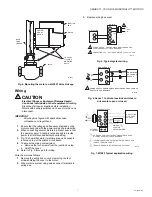
Page 7: ...iring Wire the motor as follows 1 Remove the wiring box cover by removing the four screws holding the cover to the motor 2 Wire motor to system using quick connect terminals in wiring box 3 Replace wiring box cover Fig 5 Typical system wiring Fig 6 Series 71 optional override switches to drive motor open or closed Fig 7 M7685 Typical application wiring 1 4 20 UNC 1 in LONG MOUNTING BOLTS Q5001 VAL...

Page 8: ...y turning the motor shaft damages the gear train and stroke limit contacts Adjustable Stroke All models except for M7284C1083 M7284C1091 M7284Q1082 and M7284Q1090 When viewing from the power end of the motor the stroke potentiometer is to the far left To set the stroke to 160 maximum position turn the potentiometer fully clockwise using a 1 8 in straight blade screwdriver To set the stroke at 90 m...

Page 9: ...ce between the fully open span position current and the zero position current is defined as the operating span 6 Recheck the start and readjust the span potentiometer if necessary Turn the start potentiometer clockwise to increase the zero position 7 Recheck the span and readjust the span potentiometer if necessary Turn it clockwise to increase the full span position 8 For sequential operation as ...

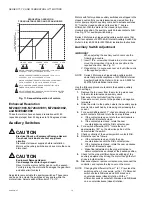
Page 10: ...ngs 1 Remove the top cover from the motor to gain access to the motor terminals and auxiliary cams 2 Disconnect the controller from the motor 3 Connect a current source to the positive and negative terminals 4 Drive the motor to the position where the auxiliary equip ment is to be switched by increasing or decreasing the current 5 For a switch differential of 1 check continuity of auxiliary switch...

Page 11: ... at the desired point of motor rotation Inspect the motor linkage and valve or damper to see that all mechanical connections are correct and secure In damper installations the pushrod should not extend more than a few inches past the ball joints Check to see that there is adequate clearance for the linkage to move through its stroke without binding or striking other objects See controller or syste...

Page 12: ...oneywell International Inc 1985 Douglas Drive North Golden Valley MN 55422 Honeywell Limited Honeywell Limitée 35 Dynamic Drive Toronto Ontario M1V 4Z9 customer honeywell com U S Registered Trademark 2010 Honeywell International Inc 63 2640 07 M S Rev 05 10 Printed in U S A ...

Reviews: