MP953A,B,C,D PNEUMATIC ACTUATORS
Manufactured for and on behalf of the Environmental and Combustion Controls Division of Honeywell Technologies Sàrl, Rolle, Z.A. La Pièce 16, Switzerland by its Authorized Representative:
Automation and Control Solutions
Honeywell GmbH
Böblinger Strasse 17
71101 Schönaich
Germany
Phone: (49) 7031 63701
Fax:
(49) 7031 637493
http://ecc.emea.honeywell.com
Subject to change without notice. Printed in Germany
EN0B-0552GE51 R1210
1
1
1
2
2
2
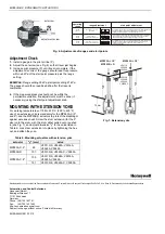
ALL screws “1” and “2”
tightened.
Three screws “1”
backed off to friction stop.
ALL screws “1” and “2”
backed off to friction stop.
70 kPa
(10 psi)
35 kPa
(5 psi)
21 kPa
(3 psi)
operating
range
range adjustment
start point adjustment
One graduation of scale on the start point adjustment knob represents a
start point change of 7 kPa. One complete turn of the start point
adjustment knob represents a start point change of 7 kPa.
One graduation of scale on the start point adjustment knob represents a
start point change of 2 kPa. Three complete turns of the start point
adjustment knob represent a start point change of 62 kPa
(note auxiliary scale).
One graduation of scale on the start point adjustment knob represents a
start point change of 3.5 kPa. Two complete turns of the start point
adjustment knob represent a start point change of 70 kPa.
adjustment screw
set screw
Fig. 6. Adjustments of ranges and start points
Adjustment Check
1.
Install a gauge in the pilot air line (P).
2.
Adjust the set screw (see Fig. 6) so that travel just begins.
3.
Increase pilot pressure (P) until travel is complete. If the
adjustment is correct, the gauge should read this pressure
within ±5 kPa of the start point pressure plus the range
setting.
EXAMPLE:
Range setting 35 kPa start point setting 21 kPa.
The gauge should then read 56±5 kPa after the travel is
completed.
4.
If the measured pressure should not be within the
permissible variation, fine adjustments must be done (if
necessary) using the start point adjustment knob.
MOUNTING WITH EXTENSION YOKE
For working temperatures of 150 to 220 °C (300 to 425 °F),
use of an extension yoke is mandatory for the MP953A,C (5"
and 8") and the MP953B,D actuators to protect the diaphragm
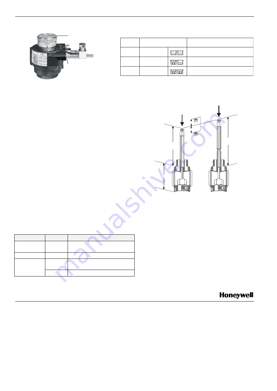
against excessive heat. Screw the stem extension (for the 5"
size) onto the stem, with the stem either pulled out or pushed
in (see Fig. 7), and adjust dimension "y" to the value listed in
Table 6. Lock stem extension into place by tightening the hex
nut, and attach the yoke.
Table 6. Mounting actuators with extension yoke
actuator
"y" (mm)
valve
MP953A,C, 5"
89
V5011R,S, V5328A, V5016A,
V5025A, V5049A
MP953B,D
107
V5013R,E, V5329A,C, V5050A
133
V5011R,S, V5328A, V5016A,
V5025A, V5049A
MP953A,C, 8"
151
V5013R,E, V5329A,C, V5050A
y
70 mm
y
C5’’
D
C8’’
V5011A
V5049A
V5328A
V5013A
V5049B
V5050A
V5329A,C
travel
travel
Fig. 7. Extension yoke

