N05010/N10010 DAMPER ACTUATORS FOR MODULATING AND FLOATING/2-POSITION CONTROL
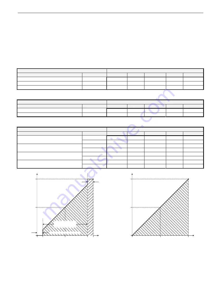
Table 1 describes, for the floating mode, the shaft adapter
behavior ("stops," rotates "CCW," or rotates "CW") in
dependence upon the control signals applied to terminals 3
and 4 and upon the function selection switch setting.
Table 2 describes, for the 2-position mode, the shaft adapter
behavior ("stops," rotates "CCW," or rotates "CW") in
dependence upon the control signals applied to terminals 3
and 4 and upon the function selection switch setting.
Table 3 describes, for the modulating mode, the shaft adapter
behavior ("stops," rotates "totally CCW," rotates "totally CW,"
runs to "proportional" position, or runs to "50%" of max.
stroke) in dependence upon the control signals applied to
terminals 3 and 4 and upon the function selection switch
setting.
Table 1. Shaft adapter behavior in the floating mode
control signal at
switch settings
terminal 3
terminal 4
0[2]...10 V
Dir
Service / Off
Rev
10...0[2] V
open open
-- stops
stops
stops --
open 24
Vac/dc
-- CCW
stops CW --
24 Vac
open
-- CW
stops
CCW --
Table 2. Shaft adapter behavior in the 2-position mode
control signal at
switch settings
terminal 3
terminal 4
0[2]...10 V
Dir
Service / Off
Rev
10...0[2] V
24 Vac
open
-- CW
stops
CCW --
24 Vac
24 Vac/dc
-- CCW
stops CW --
Table 3. Shaft adapter behavior in the modulating mode
control signal at
switch settings
terminal 3
terminal 4
0[2]...10 V
Dir
Service / Off
Rev
10...0[2] V
open
totally CCW
--
stop
--
totally CCW
open
24 Vac/dc
50% -- stop -- 50%
open
totally CCW
--
stop
--
totally CW
< min. control signal plus 0.24 V
24 Vac/dc
50% -- stop -- 50%
open
proportional
-- stop --
proportional
between min. control signal plus 0.24 V
and max. control signal minus 0.24 V
24 Vac/dc
50% -- stop -- 50%
open
totally CW
--
stop
--
totally CCW
> max. control signal minus 0.24 V
24 Vac/dc
50% -- stop -- 50%
0
0.24
0
50
100
5.0
10.0
9.76
upper dead band (9.76 to 10.0 V)
control signal (V)
fin
a
l
po
si
ti
on of sha
ft ada
pt
er
(% of ma
x.
stroke
)
range of proportional
actuator movement
(0.24 to 9.76 V)
lower dead band (0 to 0.24 V)
Fig. 4. Final shaft adapter position in dependence upon
control signal (example function selection switch setting
of 0...10 V)
0
0
50
100
5
10
feedback signal (V)
cur
rent
po
s
it
io
n
of
sh
af
t
a
dap
te
r (
%
o
f max.
str
o
k
e
)
Fig. 5. Feedback signal in dependence upon current
position of shaft adapter (example function selection
switch setting of 0...10 V)
3
EN0B-0478GE51
R0105


