SmartAct N20010, N34010
EN0B-0341GE51 R0307
2
MODELS
order number
supply voltage
end switches
control signal
feedback
torque
N20010
24 Vac
--
0...10 Vdc / 0...20 mA 0...10 Vdc 20 Nm (177 lb-in)
N20010-SW2
24 Vac
2
0...10 Vdc / 0...20 mA 0...10 Vdc 20 Nm (177 lb-in)
N34010
24 Vac
--
0...10 Vdc / 0...20 mA 0...10 Vdc 34 Nm (300 lb-in)
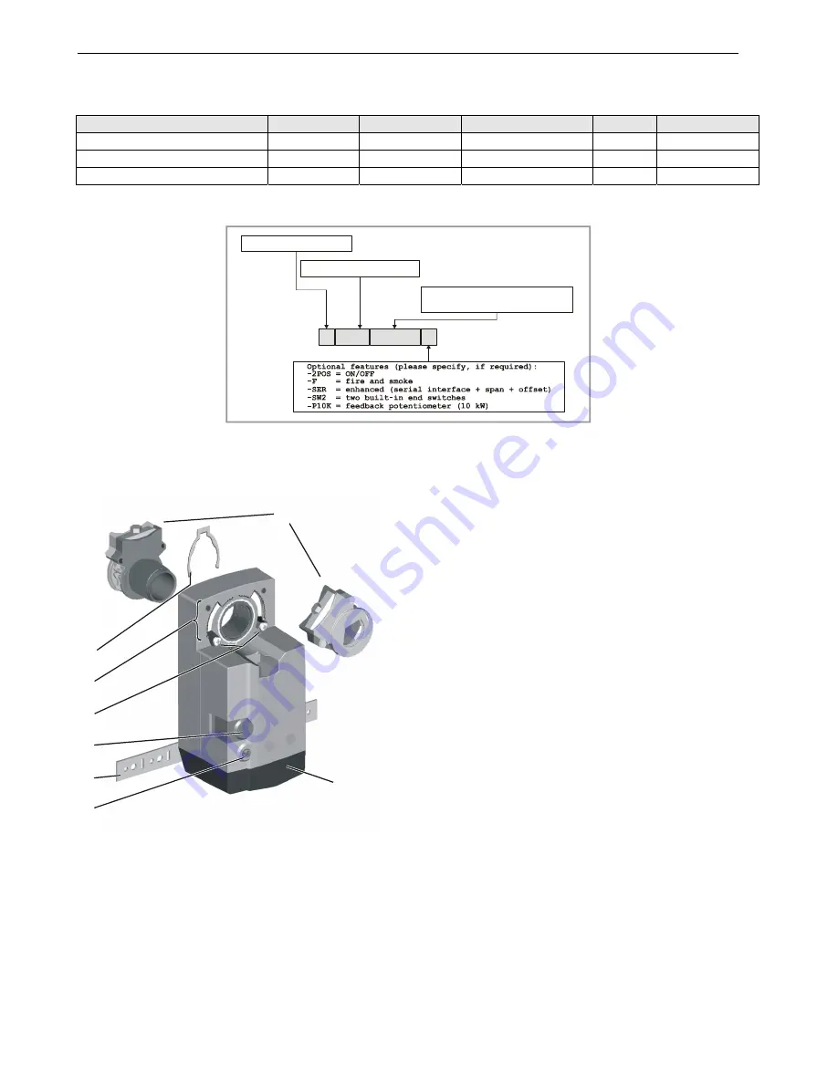
Product Identification System
SmartAct
N
3
2
0
2 0
X
N = non-spring return
S = spring return
20 = 20 Nm (177 lb-in)
34 = 34 Nm (300 lb-in)
010 = modulating
24 = 24 V fON/OFF
230 = 230 V fON/OFF
Fig. 1. Product Identification System
OPERATION / FUNCTIONS
2
3
4
5
6
7
8
30
60
60
90 90
0
30
0
1
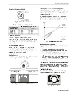
Fig. 2. Setting units and control elements
Legend for Fig. 2:
1
Self-centering shaft adapter
2 Retainer
clip
3
Rotational angle scales (0...90° / 90...0°)
4
Mechanical end limits (20 Nm [177 lb-in] models, only)
5 Declutch
button
6 Anti-rotation
bracket
7
Rotation direction switch
8 Access
cover
Contents of Package
The delivery package includes the actuator itself, parts 1
through 8 (see Fig. 2), the anti-rotation bracket screws, and
the SM mounting plate and screws.
Modulating Control
The actuator is capable of being operated by several
controllers providing Vdc or mA output.
Rotary Movement
The control signal and the corresponding rotation direction
(clockwise or counterclockwise) can be selected using the
rotation direction switch (see part 7 in Fig. 2), thus eliminating
the need to re-wire. To ensure tight closing of the dampers,
the actuator has a total rotation stroke of 95°.
As soon as operating power is applied, the actuator may start
to run. When power is removed, the actuator remains in
position. For actuator-controller wiring instructions, see
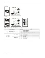
section "Wiring" on page 5.


