background image

SmartAct N20010, N34010


 3 

EN0B-0341GE51 

R0307 

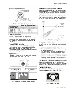
Rotation Direction Switch 


Fig. 3. Rotation Direction Switch 


Table 1. Feedback/control signal values 

feedback/control signal when 

actuator is 

rotation direction 

switch position 

totally 


totally 


Y=2

/2...10V 

U =  2 V 

U = 10 V 

Y=0

/0...10V* 

U =  0 V 

U = 10 V 

Y=0

/10...0V 

U = 10 V 

U =  0 V 

Y=2

/10...2V 

U = 10 V 

U =  2 V 

* Default shipping position. 
 

Feedback Signal and Manual Adjustment 

If, while the actuator is not rotating, the user declutches it and 

manually repositions the shaft adapter, the feedback signal 

will then follow the new position at which the shaft adapter 

has been left. 


Power OFF/ON Behavior 

In case the power to the actuator fails, after re-applying 

power, the actuator aknowledges its present position and 

follows the signal from the controller. This makes it 

unnecessary for the actuator to employ autoadaption in order 

to re-map the control signal settings. 


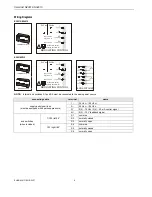
Dip Switches 

The actuators are equipped with two dip switches accessible 

after removing the access cover (see Fig. 4). 


voltage/current control signal

dip switch (

)

OFF

autoadapt dip switch for

normal operation (

)

ON


Fig. 4. Dip switches (view with PCB at bottom) 


Autoadapt Dip Switch for Normal Operation 

In its default shipping position, the autoadapt dip switch for 

normal operation is set to 

ON

 as shown in Fig. 4. If it is set to 

OFF, no autoadapting is performed, and the control signal 

map remains constant. 


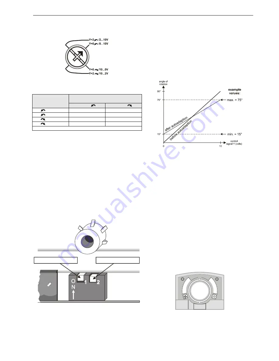
The autoadapt functionality does not have to be triggered. 

Rather, the SmartAct actuator does this automatically when 

the min. and max. control signals are provided (see Fig. 5); 

the feedback signal is likewise autoadapted. 


Fig. 5. Actuator positioning curve 


Adjusting the Actuator for Autoadapt 

In order to make use of the autoadapt functionality, proceed 

as follows: 


1.  Set the autoadapt dip switch to the ON position. 

2.  If necessary, limit the stroke to the desired range using 

the mechanical end limits. 

3.  Drive the actuator to the left end limit (totally counter-

clockwise) by setting the control signal as specified in 

Table 1. 

4.  Drive the actuator to the right end limit (totally clockwise) 

by setting the control signal as specified in Table 1. The 

stroke has now been limited to 0...100% of the control 

signal range. 


Voltage/Current Control Signal Selection Dip Switch 

In its default shipping position, the voltage/current control 

signal dip switch (see Fig. 4) is set to 

OFF

 (= voltage control). 

as shown in Fig. 4. Setting it to ON results in current control. 


Position Indication 

The hub adapter indicates the rotation angle position by 

means of the rotational angle scales (0...90° / 90...0°). 


90 90

60

30

60

30

0

0


Fig. 6. Position indication 

Summary of Contents for N20010

Page 1: ... 60 Hz 24 Vdc 10 20 Nominal voltage 24 Vac 50 60 Hz 24 Vdc All values stated hereinafter apply to operation under nominal voltage conditions Power consumption N20010 6 VA 6 W N34010 8 VA 6 W Ambient limits Ambient operating limits 20 60 C 5 140 F Ambient storage limits 40 80 C 40 175 F Relative humidity 5 95 non condensing Safety Protection standard IP54 Protection class II as per EN 60730 1 Overv...

Page 2: ...0 90 0 4 Mechanical end limits 20 Nm 177 lb in models only 5 Declutch button 6 Anti rotation bracket 7 Rotation direction switch 8 Access cover Contents of Package The delivery package includes the actuator itself parts 1 through 8 see Fig 2 the anti rotation bracket screws and the SM mounting plate and screws Modulating Control The actuator is capable of being operated by several controllers prov...

Page 3: ...pping position the autoadapt dip switch for normal operation is set to ON as shown in Fig 4 If it is set to OFF no autoadapting is performed and the control signal map remains constant The autoadapt functionality does not have to be triggered Rather the SmartAct actuator does this automatically when the min and max control signals are provided see Fig 5 the feedback signal is likewise autoadapted ...

Page 4: ...erclockwise position 5 10 15 92 5 0 90 2 5 85 80 75 85 80 75 2 5 90 0 92 5 5 10 15 5 10 15 0 90 85 80 75 CCW internal end switch CW internal end switch actuator scale clockwise end switch scale actuator scale counterclockwise Fig 9 Internal end switches Override If terminal Y of the terminal strip see section Wiring Diagrams on page 6 is unplugged the stroke will be 0 reversing the rotation direct...

Page 5: ...ower Supply In order to comply with protection class II the power source of 24 V actuators must be reliably separated from the network power supply circuits as per DIN VDE 0106 part 101 Access cover To facilitate wiring the actuator to the controller the access cover can be detached from the actuator IMPORTANT Remove power before detaching the access cover Once the access cover has been removed pl...

Page 6: ...ting transformer 24 Vac 24 Vdc END SWITCHES S1 S2 S3 S4 S5 S6 S3 S2 S6 S5 S4 S1 TERMINAL STRIP 1 END SWITCHES NOTE Internal end switches S1 and S4 must be connected to the same power source connecting cable terminal name 1 24 Vac 24 Vdc 2 24 Vac 24 Vdc 3Y 0 2 10 Vdc 0 4 20 mA control signal supply and signal lines must be equipped with spark suppressors 4U 0 2 10 V feedback signal S1 common S2 nor...

Page 7: ...w 2 cable connectors 2 dust protection caps SPARE PARTS Spare Parts Kit Order no A7209 2071 The spare parts kit contains the following items Anti rotation bracket and screws SM Mounting plate and screws Access cover screw Plastic protective cap for protection standard IP54 Mechanical end limit screw and retainer Anti Rotation Bracket Kit Order no A7209 2073 The anti rotation bracket kit can be ord...

Page 8: ...1 Schönaich Phone 49 7031 63701 Fax 49 7031 637493 http europe hbc honeywell com Subject to change without notice Printed in Germany Manufacturing location certified to EN0B 0341GE51 R0307 DIMENSIONS 60 30 0 90 shaft adapter shaft adapter reverse anti rotation bracket 100 mm 3 15 16 20 6 mm 1 3 16 48 mm 1 7 8 95 223 mm 8 25 32 92 mm 3 5 8 1000 mm 39 5 mm 0 05 0 10 mm 25 128 0 002 0 004 2 mm 5 64 2...

Reviews: