11”
Fold
Fold
Fold
17”
Fold
Fold
Fold
EN | 2
EN | 1
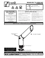
HARDWARE INCLUDED
EN | 3
F:
Washer (1)
8.5 mm x 5.2 mm x 1 mm
A:
Phillips Head Screws (2)
8-32UNC x 20
D:
Mounting Bracket (1)
100 mm x 21 mm
B:
Wire Nut (3)
P2 10 mm x 17.2 mm
E:
Phillips Head Screws (1)
M5 x 42mm
(Figure 2)
C:
Gasket (1)
Ø132 mm x 3 mm
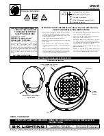
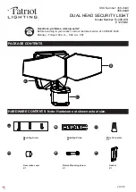
G - Light fixture
H - Motion Sensor Head
PARTS
PLANNING INSTALLATION
•
Turn off the electrical power at the fuse or circuit breaker box before installing or servicing
any part of this fixture.
•
Carefully remove the fixture from the carton and check that all parts are included. Be careful
not to misplace any of the screws or parts needed for installing the fixture.
SAFETY INFORMATION
PRE-INSTALLATION
•
To reduce the risk of electrical shock or other personal injury, ensure the power is turned
OFF at the fuse or breaker box before making any electrical connections.
•
Must be connected to 120 volt, 60 Hz power source.
•
Fixture should be mounted to a grounded junction box marked for use in wet locations.
•
Suitable for wall mount.
•
NOT suitable for ground locations. Minimum of 6 feet or higher.
WARNING:
Read all safety precautions and installation instructions carefully before installing or
servicing this fixture. Failure to comply with these instructions could result in a potentially fatal electric
shock, fire, and/or property damage.
IMPORTANT:
lisez attentivement toutes les précautions de sécurité et les installations avant
d'installer ou de réparer ce luminaire. Le non respect de ces instructions peut entraîner un choc
électrique et / ou des dégâts matériels potentiellement fatals.
SUITABLE FOR WET LOCATIONS ! CONSULT A QUALIFIED ELECTRICIAN TO ENSURE
CORRECT BRANCH CIRCUIT CONDUCTOR! MINIMUM 90° C SUPPLY CONDUCTORS!
ADAPTÉ AUX LIEUX MOUILLÉS! CONSULTER UN ÉLECTRICIEN QUALIFIÉ POUR
ASSURER UN CONDUCTEUR DE CIRCUIT DE BRANCHE APPROPRIÉ! CONDUCTEURS
D'ALIMENTATION MINIMUM DE 90° C!
CAUTION- RISK OF FIRE
THIS PRODUCT MUST BE INSTALLED IN ACCORDANCE WITH THE APPLICABLE INSTALLATION CODE
BY A PERSON FAMILIAR WITH THE CONSTRUCTION AND OPERATION OF THE PRODUCT AND THE
HAZARDS INVOLVED.
ATTENTION – RISQUE D'INCENDIE
CE PRODUIT DOIT ÊTRE INSTALLÉ SELON LE CODE D’INSTALLATION PERTINENT, PAR UNE PERSONNE
QUI CONNAÎT BIEN LE PRODUIT ET SON FONCTIONNEMENT AINSI QUE LES RISQUES INHÉRENTS.
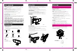
INSTALLATION
MOUNTING THE FIXTURE
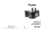
1. Secure mounting bracket (D) to junction box by attaching screws (A) through mounting bracket
and tightening to junction box. (Figure 1)
2. Insert the washer (F) into the center hole of the light fixture (G).
3. Insert phillips head screw (E) into the center hole of the light fixture (G) and the gasket (C).
Secure to the mounting bracket (D).
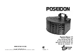
4. Apply silicone caulk (not included) around the edges of the cover plate to provide a watertight
seal from rain and moisture. (Figure 2)
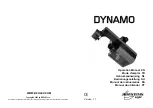
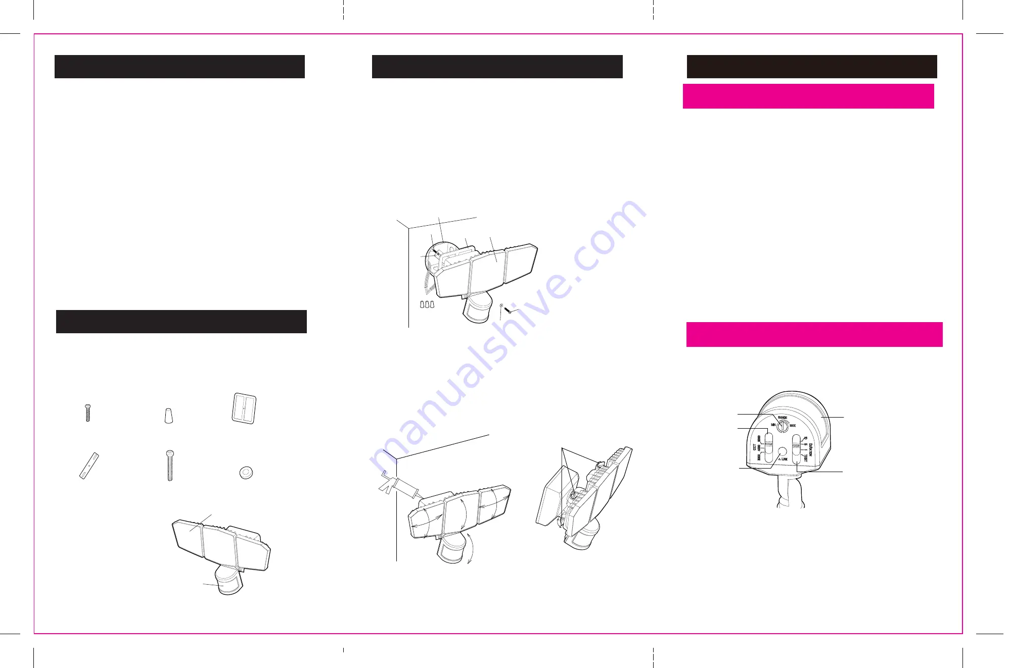
FUNCTION SWITCH:
J - Range Knob
K - Timer Switch
L - Link Button
I - CCT Switch
CAUTION:
Before beginning installation turn off the circuit breaker and light switch.
This fixture is suitable for wall or eave mount only. Not suitable for ground mount installation.
IMPORTANT: Do not use with dimmers or timers.
•
Junction box (not included) is required for the assembly.
•
• For best performance, mount the fixture recommended height of 8-12 feet above the ground.
CONNECTING THE WIRES
1. Route the fixture BLACK, WHITE and GROUND wires through the gasket (C). Remove adhesive
from gasket and adhere to light fixture (G) mounting plate.
2. Connect the AC wires to the corresponding wires (BLACK to BLACK, WHITE to WHITE and
GROUND to GROUND) in the junction box (not included) using the wire nuts (B).
RECOMMENDED:
Wrap each wire nut with electrical tape (not included) after wires
have been attached.
NOTE:
The detection angle of the light is 270 degrees. Lights should not be placed
more than
98 feet
apart otherwise linking function will not work properly. If you
purchase a light after initial installation and want to link you can restart the process
to add new light to your linked network.
INSTALLATION
NOTE:
Avoid aiming the control at:
• Objects that change temperature rapidly to prevent false triggering, such as heating vents and
air conditioners.
• Moving objects such as trees and street traffic.
TESTING THE LIGHT FIXTURE
CAUTION:
Make sure the motion sensor head is not UPSIDE DOWN.
• Turn on the circuit breaker and light switch.
• To adjust the fixture’s sensitivity to motion, rotate the RANGE knob (J) clockwise to increase
sensitivity and counterclockwise to reduce the sensitivity.
• To set the amount of DURATION you want the lights to stay on after the motion is detected, slide
duration (K) to point to the desired time setting (1min/5min/10min).
NOTE:
When first turned on wait about 1 minute for the circuitry to calibrate.
• Slide duration (K) to TEST position on back of the motion sensor head (H). (Figure 3)
• Aadjust the motion sensor head (H) toward desired detection area.
• Walk through the coverage area at the farthest distance you wish your detector to detect
motion
(max 39.4 ft)
.
NOTE:
The both sides lamp heads can be adjusted up/down and left/right and middle lamp heads can
only be adjusted up/down for optimal lighting coverage. The motion sensor can be adjusted up/down
toward desired detection area.
LINK SET-UP:
1. Up to 6 lights can be connected. Make sure all lights are powered on and set to
the TEST position. Select one light to act as parent and others as child lights.
2. Press the link button (L) of the child light. Light should be flashing. Repeat for
all child lights.
3. Press link button (L) of the parent light for a minimum of 3 seconds and wait for light to flash.
4. All linked lights will flash and then stop flashing confirming they are now linked.
G
H
(Figure 3)
(Figure 1)
CCT SWITCH
Color Temperature Presets will set light to 3000k (Warm White), 4000k (Bright White) or 5000k (Daylight)
Junction Box
(Not Included)
A
D
C
G
E
F
B
SILICONE CAULKING
(Not Included)
Knob
J
H
K
L
I