Installing the Network Gateway Unit
(Continued)
3
X
X
D
D
A
A
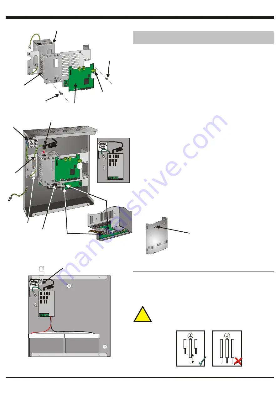
Fitting a PSU3A (Kit PN: 020-648) - Optional
This procedure assumes that the chassis has been removed from the back
box - see ‘Preparing the Back Box’.
1
Disconnect the dc connector (A) from the Network Gateway Module
(NGM) - (B).
2
Remove and retain the four M3 X 8 SEM screws (C) that secure the NGM
to the chassis, then remove the NGM and store it safely (take anti-static
precautions).
3
Orientate the PSU3A (D) as shown and secure it to the chassis using the
M4 x 8 SEM screws (E) supplied with the PSU3A.
4
Replace the NGM onto the chassis (by reversing steps 2 and 1 above),
then replace the chassis in the back box.
Ensure the chassis earth
connection is remade.
5
Push the connector of the PSU3A mains cable (F) into the socket on the
PSU3A [the other end of the mains cable is factory-fitted to the mains
terminal block (G)]. Ensure the mains cable is routed as shown in the
illustration. Pull tight the cable clip at the side of the back box.
6
Connect the PSU earth lead (H) to the upper blade on the back box.
7
Connect the 4-way power cable (I) and 10-way ribbon cable (J) (supplied
with the NGU) between the PSU3A and the PSU3A to Network Interface
PCB.
8
Use the supplied cable tie to secure the ribbon cable’s ferrite (K) to the tie
point on the chassis.
9
Remove and discard the PSU rating label (L) from the chassis.
10
Remove and discard the NGU product label (M) from the cover. Peel off
the backing from the NGU EN54-compliant label supplied in the NGU
accessory kit, and attach the label to the cover in place of the removed
label.
Fitting a PSU3A (Kit PN: 020-648) - Optional
This procedure assumes that the chassis has been removed from the back
box - see ‘Preparing the Back Box’.
Disconnect the dc connector (A) from the Network Gateway Module
(NGM) - (B).
Remove and retain the four M3 X 8 SEM screws (C) that secure the NGM
to the chassis, then remove the NGM and store it safely (take anti-static
precautions).
Orientate the PSU3A (D) as shown and secure it to the chassis using the
M4 x 8 SEM screws (E) supplied with the PSU3A.
Replace the NGM onto the chassis (by reversing steps 2 and 1 above),
then replace the chassis in the back box.
Push the connector of the PSU3A mains cable (F) into the socket on the
PSU3A [the other end of the mains cable is factory-fitted to the mains
terminal block (G)]. Ensure the mains cable is routed as shown in the
illustration. Pull tight the cable clip at the side of the back box.
Connect the PSU earth lead (H) to the upper blade on the back box.
Connect the 4-way power cable (I) and 10-way ribbon cable (J) (supplied
with the NGU) between the PSU3A and the PSU3A to Network Interface
PCB.
Use the supplied cable tie to secure the ribbon cable’s ferrite (K) to the tie
point on the chassis.
Remove and discard the PSU rating label (L) from the chassis.
Remove and discard the NGU product label (M) from the cover. Peel off
the backing from the NGU EN54-compliant label supplied in the NGU
accessory kit, and attach the label to the cover in place of the removed
label.
1
2
3
4
Ensure the chassis earth
connection is remade.
5
6
7
8
9
10
TRANSIT CABLE CLIP: Before proceeding, CAREFULLY cut the cable
clip that secures the ferrite cable loop to the chassis (at 'X' on drawing).
TRANSIT CABLE CLIP: Before proceeding, CAREFULLY cut the cable
clip that secures the ferrite cable loop to the chassis (at 'X' on drawing).
B
B
C
(typical 4
locations)
C
(typical 4
locations)
E
(typical 4
locations)
E
(typical 4
locations)
G
G
F
F
NN
LL
F - in detail
F - in detail
H
H
II
J
J
K
K
PSU3A
PSU3A
Wiring Connections - Mains and Safety Earth
Live and Neutral must only be connected if the PSU3A is fitted.
The earth
connection must always be connected.
Cables are to be brought into the
back box using 20mm knockouts and appropriate glands - (refer to the panel’s
Installation & Commissioning manual) in accordance with local standards.
Terminate the mains/earth at the terminal block; connections are labelled.
!!
Segregate mains wiring from all other wiring.
When terminating mains leads, ensure that the earth lead is
longer than L and N.
Segregate mains wiring from all other wiring.
When terminating mains leads, ensure that the earth lead is
longer than L and N.
>25mm
L
N
L
N
L
L
M
M
997-451, Issue 6 July 2006
NN
LL
FOR CLARITY, SHOWN WITH
CHASSIS REMOVED
FOR CLARITY, SHOWN WITH
CHASSIS REMOVED
MAINS
WIRES
MAINS
WIRES


