ID2000 Series Installation & Commissioning Manual
Installation Guide
10
997-433-000-5, Issue 5
May 2010
2
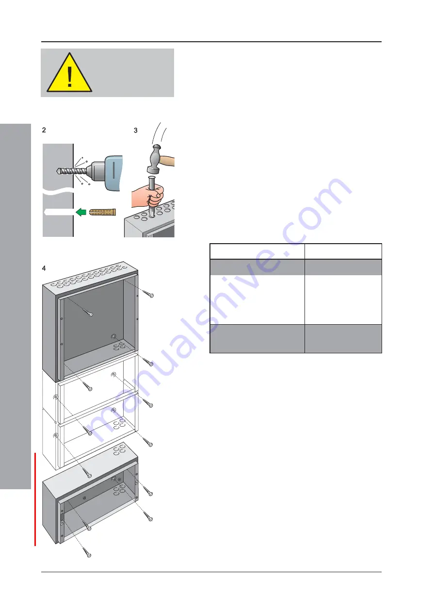
Using a suitable-sized drilling bit - for holes to take up
to 6mm (No.12-sized) wood screws - drill the required
number of holes.
3
Prepare apertures (20mm knockouts) required for
cable access.
4
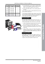
Screw the panel back box to the wall using all fixing
holes and appropriate-sized screws. The back box
fixing holes can take up to 6mm (size No.12) round-
or pan-headed screws (DO NOT use countersunk
screws).
Note:
Make sure the screw in the keyhole is driven fully
into the recess to avoid impacting the main chassis
when this is being fitted.
The number of screws required depends on the size
of the back box. The recommended screw quantities
are as follows:
Back Box Part Number
Screw Quantity
020-472-XXX
4
020-473-XXX
6
020-474-XXX
6
020-475-XXX
8
020-476-XXX
8
020-508-XXX
4
020-509-XXX
4
DO NOT use the back
box as a guide when
drilling.
2.4.4 Electronics Modules
The ID2000 Series panel electronics modules, i.e. the
main chassis, which contains all processing, user-
interface and input/output processing PCBs, and either
the Power Supply Unit (PSU) or Dual Transmission Path
(DTP) unit, are supplied as separate, self-contained
assemblies. These modules are fitted in the panel back
box once all site power distribution and fire detection loop
cabling has been provided, in accordance with the system
design requirements and applicable local standards.

