ID2000 Series Installation & Commissioning Manual
Inst
allation - Panel Electronics
23
997-433-000-5, Issue 5
May 2010
5.3 Dual Transmission Path/Booster Module
The Dual Transmission Path (DTP)/Booster module is very
easy to fit to the main chassis, providing the instructions
described below are followed. The DTP/Booster module is
located in an open, rear compartment of the main chassis and
MUST be fitted before installing the main chassis in the back
box. The DTP/Booster module is secured to the main chassis
using four M4 x 8 SEM screws. A 4-wire cable supplied with
the module for backward compatibility is not required and
should be discarded.
Check Your Equipment....
Before proceeding with the DTP/Booster installation, first
remove all packaging and inspect for any damage which may
have occurred in transit. If no damage is evident, proceed
with the installation of the DTP/Booster module.
A Cautionary Note....
During this procedure, various wiring connections are made
and it is important that the manufacturer’s recommendations
are followed to avoid the possibility of damage occuring
when fitting the PSU DTP/Booster module.
5.3.1 Procedure
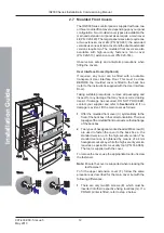
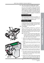
Place the DTP/Booster module (A) on a clean work
surface so that the side with the ‘rating’ label (B) is
uppermost (see drawing at left) - this side is provided
with four holes (C) for fitting the module. With the module
temporarily supported in this position, fit the main chassis
assembly (D) as follows:
Note:
If the PSU is located in the back box, perform ‘Other
Wiring Connections’ step ‘a’ at the DTP/Booster
module end of the connection NOW. Access to the
ribbon cable connector becomes more difficult after
the module is fitted to the main chassis.
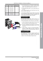
1
With the main chassis orientated with the front door
uppermost, carefully lower it until the part to the right
of the front door hinge rests on the DTP/Booster
module.
2
Line the four holes (E) on the front face of the main
chassis with the corresponding holes (C) on the
module.
3
Taking care not to trap the module’s cables and the
earth wiring, insert the four M4 x 8 SEM screws (F)
and, using a No.2 Posidriv screwdriver, tighten them
until the module is secured firmly to the main chassis.
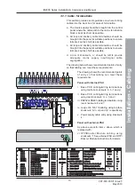
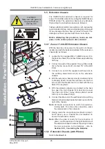
With the module now secured, take the module’s two
cables into the main chassis’ PCB enclosure as follows:
4
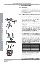
First, ease the connector of the 10-way ribbon cable
(G) and the connector of the power cable (H) through
the aperture (I) in the main chassis. Pull the cables
through, taking up any slack.
5
Secondly, with a sufficient length of each cable pulled
through, to connect to the Base PCB, ease the
grommet (J) in to the aperture (I) and then slide it and
the cables sideways into the circular part until secure.
A
D
E
B
F (x4)
F (x4)
C (x4)
C (x4)
1


