ID2000 Series Installation & Commissioning Manual
Inst
allation - Panel Electronics
30
997-433-000-5, Issue 5
May 2010
5.8 Base PCB
The ID2000 Series Base PCB is located on the rear face
of the main chassis PCB enclosure. In the unlikely event
that the Base PCB becomes faulty and needs to be replaced
a replacement kit (PN: 020-568) is available. To replace
the Base PCB, the manufacturer recommends the removal
of the main chassis from the back box, as adequate space
is required for the Base PCB removal process.
Before starting, make sure you have a PC back-up
of the panel’s current configuration data.
Ensure you take appropriate anti-static precautions
before undertaking this procedure.
1
Assuming the front cover moulding has been
removed, disconnect ALL power to the ID2000 Series
control panel - disconnect the batteries first and
isolate the mains supply input - before continuing.
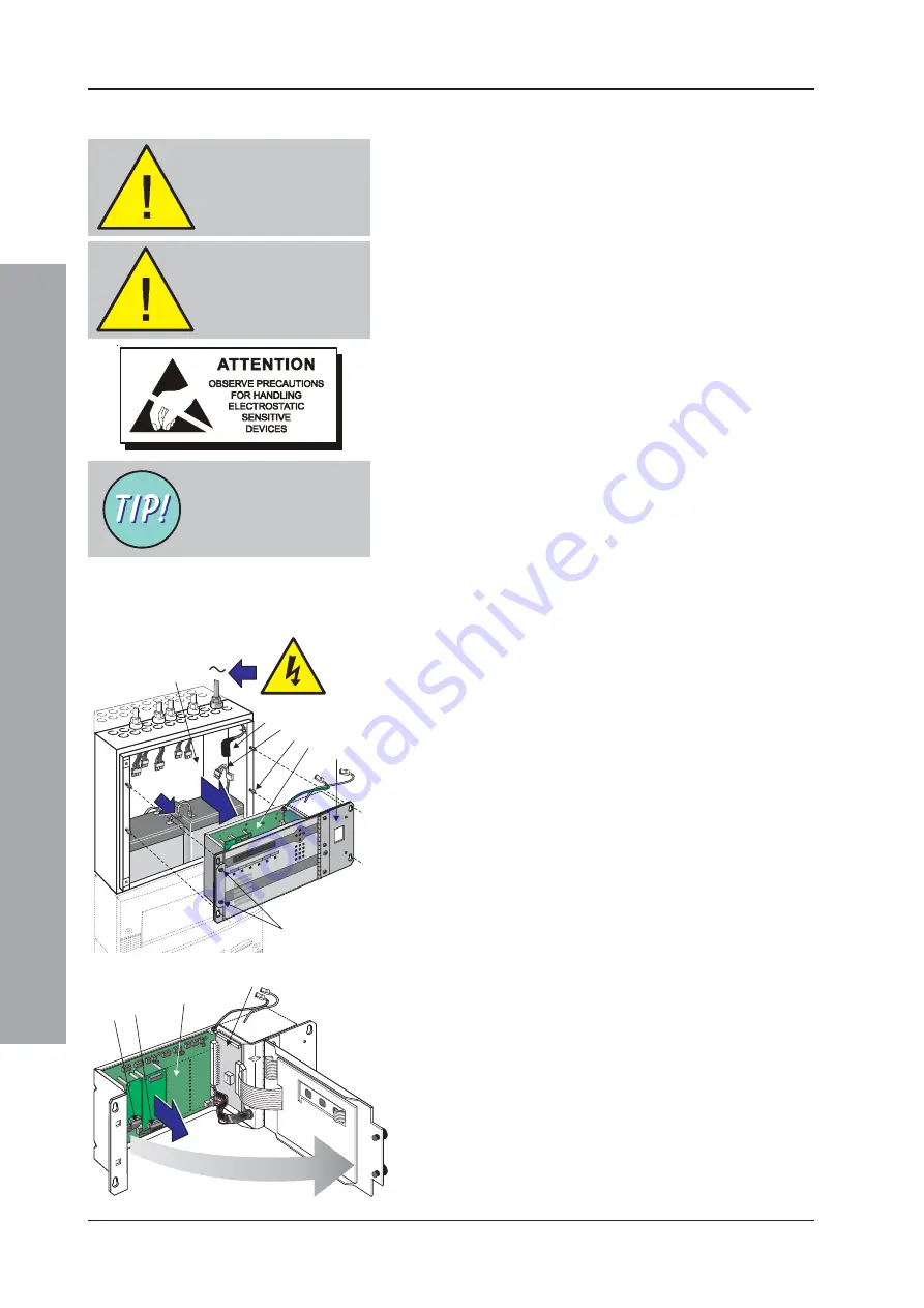
Disconnect the power lead (A), and the battery
charger and thermistor leads (B), from either the PSU
module or the DTP/Booster module (not shown).
2
Using a suitable-sized coin, release the two quarter-
turn fasteners (C), and open the main chassis’ hinged
door to access the main chassis PCB enclosure.
3
At the Base PCB (D), disconnect all cable and wiring
terminations (see
Section 5.8.2, Cables and
Wiring
). Close the hinged door and secure using the
quarter-turn fasteners.
4
Using a Posidriv screwdriver, loosen the four main
chassis retaining screws (E). Remove the main chassis
(F) from the back box (G), and place on a clean work
surface with the front door uppermost. Open the front
door to gain access to the Base PCB (D).
5
Remove any 3rd-layer PCB(s), if fitted - refer to the
appropriate installation section of the manual.
6
Disconnect the short ribbon cable (H or J) to any 2nd-
layer Module PCBs (if fitted) and remove the PCB(s)
- refer to
Sections 5.11
and
5.12
- and place in an
anti-static bag. Keep safe until required for re-fitting.
Note:
If fitted, make a note of the position of the Module
PCBs for re-fitting.
7
Remove the Processor PCB (K) from the main
chassis - refer to
Section 5.9
for details. Store safely
in an anti-static bag until required for re-fitting.
8
Remove the Base PCB from the main chassis using
a No. 1 Posidriv screwdriver to remove the seven
(7) M3 x 10 SEM screws from the Base PCB. Keep
safe until required for re-fitting.
Note:
Note the locations of the user-defined links as
indicated by the two black-filled boxes in the
Cables and Wiring drawing below.
9
Remove any nylon snap-top spacers (L) for re-use on the
replacement PCB and place the Base PCB in an anti-
static bag and keep safe until ready for dispatch.
WARNING -
Disconnect power
from the ID2000
Series panel
Make sure you have
a PC back-up of the
current
configuration data
Label cables before
disconnecting.
1
4
A
D
F
C
E
B
G
1
K
D
H
J
2, 4
2, 4
6

