IDR-M Mimic Installation & Commissioning Manual
Installation Guide
14
997-412-000-3, Issue 3
June 2005
2.5.2 IDR-MD Mimic Driver Kit
2.5.2.1 Mimic Driver Board
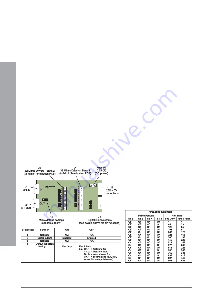
DIP Switch
The DIP switch, S1, located on the Mimic
Driver board (close to the OUT connector)
allows the functions, described in the tables
below, to be configured.
Note:
If the IDR Configuration Tool is used to
configure the IDR-M mimic, the DIP
switch (S1) settings are overridden.
The DIP switch, S1, allows the output channels
to be configured as only FIRE indications, or
as FIRE and FAULT indications using alternate
output channels. S1-4 is used to select the
required output channel indication. S1-5 to S1-
8 are used to set the zonal output channel
indications if the first zone is not Zone 1; it can
be set to a numerically-higher zone in fixed
increments of 64, for FIRE indications only, or
increments of 32, for FIRE and FAULT
indications.
Note:
Only the first Mimic Driver board’s DIP
switch settings have any effect.
Connections
The connections to this board are shown
below.


