background image

12 Clintonville Road
Northford, CT 06472-1610 USA
800-289-3473 • FAX 203-484-7118
www.notifier.com

NFS-320 and NFS-320SYS 

Listing Document

PN 52745LD:G9   5/19/2022   16475

For additional documentation on this product, visit http://notifiermanuals.com. This additional documentation for the NFS-320 may be used as a refer-
ence only.       

1 Installation

Wiring methods used shall be in accordance with Standard for Installation and Classification of Burglar and Holdup Alarm Systems, UL 681.
Wiring methods used shall be in accordance with Standard for Central Station Alarm Services, UL 827.
This product is intended to be installed in accordance with the following:

Follow these guidelines when mounting the product’s backbox:

Backbox should be installed in a dry, indoor location.

It is recommended that this system and its peripherals be installed in an environment with a normal room temperature of 15-27°C/60-80°F and at 

a relative humidity of 93% ± 2% RH (non-condensing) at 32°C ± 2°C (90°F ± 3°F).

Locate the backbox so the top edge is 66 inches (1.6764 m) above the surface of the finished floor.

Access to the cabinet shall be in accordance with NFPA 90, article 110.33.

Allow sufficient clearance around cabinet for door to swing freely.

Use cables provided to connect dress panel(s) and cabinet door to earth ground.


NOTE:

The term NFS-320 is used to refer to the NFS-320, NFS-320E, NFS-320C, and NFS-320SYS unless otherwise noted.

NOTE:

For Mass Notification applications, Class A circuits called out in this manual are Class X.

NFPA 70 - National Electrical Code

NFPA 16 - Standard for Deluge-Foam Water Systems

NFPA 72 - National Fire Alarm Code

NFPA 17 - Standard for Dry Chemical Extinguishing Systems

NFPA 12 - Standard on Carbon Dioxide Extinguishing Systems

NFPA 17A - Standard for Wet Chemical Extinguishing Systems

NFPA 12A - Standard on Halon 1301 Fire Extinguishing Systems •

NFPA 2001 - Standard for Clean Agent Fire Extinguishing Systems

NFPA 13 - Standard for Installation of Sprinkler Systems

UL 2610 - Standard for Commercial Premises Security Alarm Units and 

Systems

Canadian Electrical Code, Part I

NFPA 15 - Standard for Water Spray Fixed Systems

ULC S524 - Standard for the Installation of Fire Alarm Systems •

ULC S561 - Installation and Services for Fire Signal Receiving Centers 

and Systems

NFPA 2010 - Standard for Fixed Aerosol Fire Extinguishing 

System

ULC-S527-11 - Standard for Control Units for Fire Alarm Systems

NFPA 92 - Standard for Smoke-Control Systems

UL 864 Standard for Control Units and Accessories for Fire Alarm 

Systems, 10th Edition

UL 2572 - Standard for Mass Notification Systems

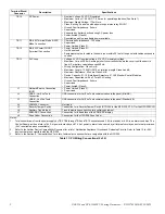
Terminal Block/

Connector

Description

Specifications

TB4

Alarm & Trouble Output Relays -
Common

• Power-limited (Class 2) only if connected to a power-limited source
• Voltage and Current: Rated 2.0 A at 30 VDC resistive
• Non-supervised

TB5

Supervisory & Security Output 
Relay - Common or 
programmable

• Power-limited (Class 2) only if connected to a power-limited source
• Voltage and Current: Rated 2.0 A at 30 VDC resistive
• Can be programmed as Alarm via VeriFire Tools
• Non-supervised

TB6 thru TB9

NAC Circuits

• Nominal Operating Voltage: 24 VDC Regulated
• Maximum Current: 1.5A (See Note 1)
• End-Of-Line Resistors: 2.2 K 1/2 W (ELR-2.2K)
• Wiring Configuration: Class B or Class A
• Ground Fault Impedance: 0 ohms
• Maximum Line Impedance: 20 ohms
• Supervised
• Power-limited (Class 2)

Table 1  CPU Wiring Connections (1 of 2)

Summary of Contents for Notifier NFS-320

Page 1: ...Systems NFPA 72 National Fire Alarm Code NFPA 17 Standard for Dry Chemical Extinguishing Systems NFPA 12 Standard on Carbon Dioxide Extinguishing Systems NFPA 17A Standard for Wet Chemical Extinguishing Systems NFPA 12A Standard on Halon 1301 Fire Extinguishing Systems NFPA 2001 Standard for Clean Agent Fire Extinguishing Systems NFPA 13 Standard for Installation of Sprinkler Systems UL 2610 Stand...

Page 2: ...mpedance 0 ohms Supervised Power limited Class 2 J1 Network Service Connection NUP Power Limited Class 2 Supervised J2 USB A VeriFire Tools Connection USB connection for VeriFire Tools communication to the panel Mini AB J3 USB B VeriFire Tools Connection USB connection for VeriFire Tools communication to the panel Standard B J4 LEM 320 Connector Not Used J5 Security Tamper Switch Connection for a ...

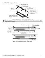
Page 3: ...S Chassis Mounting Options Slot 2 CPU CPS 24 and primary display Slot 3 Mounting location for LEM 320 or other option board Slot 4 Mounting location for option boards and other compatible peripherals Recommended mounting location for fiber versions of the NCM and HS NCM CPU CPS 24 E DP DISP2 or ADP2 640 if in lower row Primary Display KDM R2 C or NCA 2 C mounts to chassis Right Annunciator mounts ...

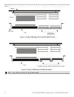
Page 4: ... mounted because of the position of the ground ing screw NOTE See the NCD Manual LS10210 051NF E for more information Option boards Mounted on BMP 1 Dress Panel NCD CPS 24 E Backbox Figure 3 Top View of Mounting an NCD in the NFS 320SYS Chassis NCD Annunciators which are attached to the fire alarm control panel Figure 4 Top View of Mounting an NCD with Annunciators ...

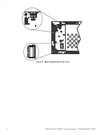
Page 5: ...gure 5 Installing the CPU on the Chassis Figure 6 Installing the Power Supply on the CPU Figure 7 Installing the KDM 2 on the CPU Figure 8 Installing Option Boards on the CPU Figure 9 Installing Option Boards on the Chassis Figure 10 Installing the Chassis into the Cabinet ...

Page 6: ...ts standoffs to secure the first option board then lay the second option board over the standoffs Two sizes of standoffs are shipped with the option boards select standoffs that allow sufficient clearance for electronics on the lower option board 4 Secure the top option board with four 4 40 screws supplied 5 Re attach KDM R2 C NOTE UDACT UDACT 2 only If using a UDACT or UDACT 2 inside the cabinet ...

Page 7: ...ACK SILENCE RESET Figure 13 CPU Wiring Connections TB13 SLC Wiring B A B A TB12 Printer Wiring TB11 EIA 485 ACS Wiring TB12 PC CRT Wiring TB11 EIA 485 Terminal Wiring TB10 24V Resettable Power TB10 24V Non Resettable Power TX RX REF XMIT REC TB9 NAC 1 A A B B A A B B TB8 NAC 2 TB7 NAC 3 TB6 NAC 4 A A B B A A B B TB5 Security Relay C C NC NO NC NO TB4 Trouble Relay TB4 Alarm Relay C NC NO C NCNO TX...

Page 8: ...8 NFS 320 and NFS 320SYS UL Listing Document P N 52745LD G9 5 19 2022 Figure 14 Power Supply Wiring Connections ...

Page 9: ...er followed by 5 minutes in alarm 3 NFPA 72 Auxiliary and Remote Station Systems require 24 hours of standby power followed by 5 minutes in alarm 4 Batteries installed in a system powered by an automatic starting engine generator need to provide at least 4 hours of standby power 5 Factory Mutual requires 90 hours of standby for deluge preaction systems 6 Emergency voice alarm communications system...

Page 10: ...LED10 SLC Loop Ground Fault LED System Switches No Keyboard Operation SW5 Acknowledge SW6 Silence SW7 Reset CPU320 KAPS 2 wmf CPU2 640 LEDs wmf JP1 SLC Ground Fault Jumper SW1 Ground Fault Detection Enable Disable LED3 Earth Fault LED general board ground fault LED5 24V Aux LED LED6 5V Aux LED LED1 Logic Power LED LED2 Trouble LED LED4 AC Power LED F4 AC Fuse LED5 Supervisory LED LED7 Pre Alarm LE...

Page 11: ...security LED and displays a security alarm condition on the primary display The panel sounder will sound until you acknowledge the Security alarm You can also program additional sounders or output devices to activate with the security alarm initiating device These type codes are designed to indicate an alarm in one or more of the following situations NOTE If additional knockouts are added to the b...

Page 12: ...onitoring station personnel when the burglar alarm system is in the armed state and as a trouble condition while the system is disarmed Refer to the SLC Wiring Manual 51253 for additional information on required wiring sizes There are five software type IDs associated with security operation ACCESS MONITOR alarm AREA MONITOR EQUIP MONITOR SECURITY L and SYS MONITOR There is also one software funct...

Page 13: ...uble arming system Contact Switch for Each Entry Exit Door RKS S Key Switch MM Monitor Modules Remote Annunciator for Each Entry Exit Door ACM 24AT ACM 48A ACM 16AT ACM 32A Security Devices RM Relay Module Compatible Printer Programming of Key Switch Access Points and Motion Detection RKS Remote Key Switch with Monitor Module Address LXXMYYY arbitrary Type ID ACCESS MONITOR Zone Map none Custom La...

Page 14: ...ogic Equation for Security Alarm ZLe AND ZLc OR ZLd Follow the following restrictions on values a b c d e 7 Programming Group Interfaces Group Interface for Trouble when system is armed while access point s active A CM programming Address LXXMYYY arbitrary Type ID RELAY Zone Map ZLb Custom Label Arming Trouble Group Output Signal Silence No Walk Test Yes No Installer Specified Switch Inhibit Yes B...

Page 15: ...ning until it snaps into place 2 Connect the STS 200 or STS 1 connector to J5 Security Tamper on the Control Panel As shown in figure 20 J5 is located on the circuit board underneath the edge of KDM R2 C NOTE When installing a Security Tamper Switch use the STS 200 for the NFS 320 For the NFS 320SYS use the STS 1 NOTE Total SLC points connected to the FACP are limited to 1000 or less for burglar a...

Page 16: ...match Protection Device to protect against high voltage transient signals such as lightning that may cause the device to accidentally release Multiple Stat X devices can be connected in series as shown No more than ten 10 Stat X devices can be connected on a single releasing circuit A REL 2 2K can be installed on a single Stat X device for short circuit detection For multiple Stat X devices instal...

Page 17: ...xed systems for fire protection NFPA 16 Foam water sprinkler and foam water spray systems NFPA 17 Dry chemical extinguishing systems NFPA 17A Wet chemical extinguishing systems NFPA 2001 Clean agent fire extinguishing systems NFPA 2010 Standard for Fixed Aerosol Fire Extinguishing System Process Control non critical Fire Alarm Event If other events exist and the panel is silenced a fire alarm will...

Page 18: ...d the MN alarm Sends an MN Alarm message to LCD Display remote annunciators History buffer installed printers and CRT 2s Latches the control panel in MN alarm Panel will not return to normal operation until a System Reset is completed Initiates any Control By Event actions Activates Special Zone ZFD Not applicable for FirstCommand applications Does not activate any alarm relays or devices programm...

Page 19: ...installed printers and CRT 2s Sends an Trouble message to the central control station via the network if applicable Displays MN TBL in the status banner on the control panel along with information specific to the device as shown below Responding to an MN trouble event 1 Press the ACKNOWLEDGE SCROLL DISPLAY key to silence the panel sounder and switch the SYSTEM TROUBLE LED from flashing to steady A...

Page 20: ...m being generated Displays ACTIVE in the status banner on the control panel along with information specific to the device Sends a Security message to the LCD display remote annunciators history buffer installed printers and CRT 2s Sends a Security message to the proprietary receiver via the network if applicable Responding to a security event 1 Press the ACKNOWLEDGE SCROLL display key to silence t...

Page 21: ...will light steady The control panel sends a Signal Silenced message to the remote annunciators history buffer installed printers and CRT 2s Check the alarm message for the location and type of event 2 Correct the condition that activated the CO alarm 3 Press the SYSTEM RESET key to return the control panel to normal operation A System Normal message is sent to the LCD display remote annunciators h...

Page 22: ...ng device circuit Polling Style Limitations Polling style is FlashScan or CLIP Classic Loop Interface Protocol Options 1 All detectors and modules on an SLC may be programmed as FlashScan All detectors and modules must be FlashScan type devices Maximum number of devices per SLC 159 detectors 159 modules 2 All detectors and modules on an SLC may be programmed as CLIP Detectors and modules may be a ...

Page 23: ...led TheNCA 2 C or ONYXWorks may be employed as a Display and Control Center In the event that communication fails between the panels and the Control Center the panels will continue to function in local standalone mode Automatic Alarm Signal Silence For a system requiring annunciators consult the Authority Having Jurisdiction Auto Silence If auto silence is enabled the value must be set to 20 minut...

Page 24: ...A M 2 N E T W OR K 3 U T IL I T Y 4 F L A S HS C A N P OL L 0 C L R 1 A U T O 2 P O I NT 3 P A SS W D 4 ME S S A G E 5 Z O N ES 6 S PL F U N C T 7 S Y S TE M 8 C HE C K P R G T HR E S H O L D C H A H T H R ES H O L D CH B H N OD E 0 0 0 CL A S S A Y E N TE R R E GI O N 0 T B L R EM I N D 2 A L A S CR O L L N L O CA L C O N TR O L 0 F L A S HS C A N L 1 D E T L 1 M O D N Y Special Zone Lets you F0 ...

Page 25: ...ss Applications Trouble Re annunciation Yes N A Yes 4 hours 24 hours N A 4 hours 4 hours Alarm Re annunciation Yes N A Yes 4 Hours 24 Hours N A 24 Hours 24 Hours Supervisory Re annunciation Yes N A Yes 4 Hours 24 Hours N A 24 Hours 24 Hours CO Re annunciation Yes N A Y N 4 Hours 24 Hours N A 24 Hours Y N Detector Programming Supervisory Type Codes Yes N A Yes SUP L DUCTI SUP T DUCTI SUP T DUCTP SU...

Page 26: ... Modules 65 128 Q Not used F Not used R Loop 1 detectors 15 46 Each detector occupies 2 points G Loop 1 Modules 129 159 1 unused point S Not used H Loop 1 Detectors 1 64 T Loop 1 Detectors 47 78 Each detector occupies 2 points I Not used U Not used J Loop 1 Detectors 65 128 V Loop 1 Detectors 79 100 Each detector occupies 2 points K Not used W Not used L Loop 1 Detectors 129 159 1 unused point Gro...

Page 27: ...e before installing the detector by referring to the manufacturer s installation instructions The nominal sensitivity displayed on the FACP is for reference only 2 FSP 951 FSP 951 IV FSP 951R FSP 951R IV FSP 951T FSP 951T IV detectors must be programmed with sensitivity level 8 or 9 for Open Area Protection and Levels 1 through 7 for Special Applications to be compliant with UL 268 7th Edition req...

Page 28: ...Y lights fire alarm LED for heat and photo alarms will light supervisory LED for CO alarm photo and heat alarms will activate CBE CO alarm will activate sixth CBE zone only sixth CBE zone programmable via VeriFire Tools Photoelectric Carbon Monoxide and Heat detector Note For FIRE CO detectors Detectors programmed as FIRE CO P SUP the heat and CO elements will latch and require a system reset to c...

Page 29: ...ights fire alarm LED and activates CBE 135o F intelligent thermal sensor HEAT ROR fire alarm Y lights fire alarm LED and activates CBE 15o F per minute rate of rise detector SMOKE ACCLIM fire alarm Y lights fire alarm LED and activates CBE Combination Photoelectric heat detector without freeze warning Acclimate Plus SMOKE ACCLI fire alarm Y lights fire alarm LED and activates CBE Combination Photo...

Page 30: ...N Performs Drill function Activates silenceable outputs EVACUATE SWITCH2 non alarm N Performs Drill function Activates all silenceable outputs FIRE CONTROL non alarm Y Activates CBE Used for non fire activation of outputs NON FIRE non alarm N Activates CBE Used for building energy management PAS INHIBIT3 non alarm N Inhibits Positive Alarm Sequence Inhibits Positive Alarm Sequence POWER MONITR tro...

Page 31: ... other Type Code applies REL CKT ULC1 N NAC Releasing Circuit power limited Class 2 supervised for opens shorts and ground faults always non silenceable RELEASE CKT1 N NAC Releasing circuit non power limited supervised for opens and ground faults RELEA FORM C1 N Form C Relay Relay output contacts operate upon release REL AUDIBLE Y NAC NAC activated upon release NONRESET CTL N Form C Relay and NAC ...

Page 32: ...e upon receipt of an alarm condition and remain in the alarm state until all alarms have been acknowledged It is programmed as switch inhibit CONTROL NAC Y Supervised NAC GEN ALARM N Control Module an XPC 8 circuit or an XP5 C in NAC mode configured as a Municipal Box Transmitter for NFPA 72 2002 Auxiliary Fire Alarm Systems applications MBT 1 required This Type ID can also be used for general ala...

Page 33: ...der Press and hold the key The panel will light all control panel LEDs turn on the panel sounder and light all segments of the LCD display If the Lamp Test key is held longer than 5 seconds the LCD will display the software revisions Operational Checks Before proceeding a notify the fire department and the central alarm receiving station if transmitting alarm conditions b notify facility personnel...

Page 34: ...c Walk Test in the following manner From the Status Change Selection screen press the 6 key The control panel displays the Walk Test screen as shown below Operate the control panel in Walk Test as follows Basic Walk Test directs the control panel to do the following Activate silenceable outputs associated by programming with each new alarm The panel does not activate non silenceable outputs Save a...

Page 35: ...asic Walk Test latches on steady red during activation If the device is put in trouble for instance the detector head is removed then replaced the LED will be latched on for the duration of the test an output device activated during Basic Walk Test will remain active and the LED will glow steady green if a FlashScan module or steady red if a CLIP module for approximately 4 seconds for alarms appro...

Page 36: ...ommunications Module Single Mode Fiber HS NCM W High Speed Network Communications Module Wire HS NCM W 2 High Speed Network Communications Module Wire HS NCM WMF High Speed Network Communications Module Wire to Multi Mode Fiber HS NCM WMF 2 High Speed Network Communications Module Wire to Multi Mode Fiber HS NCM WSF High Speed Network Communications Module Wire to Single Mode Fiber HS NCM WSF 2 Hi...

Page 37: ...PC 8 Transponder Control Module XPDP Transponder Dress Panel XPM 8 Transponder Monitor Module XPM 8L Transponder Monitor Module XPP 1 Transponder Processor XPR 8 Transponder Relay Module 7 System Configuration The following is the minimum configuration to meet NFPA UL and ULC requirements for the categories listed Module Description CS Local AUX RS P PPU P Burg REL P Rec Process Mana CPU 320 CPU 3...

Page 38: ...moke Control Expander O O O O O O O O O SCE 8L Smoke Control Lamp Driver Expander O O O O O O O O O IPDACT IP Digital Alarm Communicator O N N O N N N N N UDACT 2 Digital Alarm Communicator Y N N O O N N N N ACM 16AT Annunciator Control Module O O O O O O O O O ACM 32A Annunciator Control Module O O O O O O O O O AEM 16AT Annunciator Expander Module O O O O O O O O O AEM 32A Annunciator Expander M...

Page 39: ...ng Signal Silence Inhibit Remote annunciator outputs Automatic Alarm Signal Silence Drift compensation Detector sensitivity testing per Par 7 3 2 1 of NFPA 72 8 Required when using CGW MB alone OR using a CGW MB with CGW PT OR using CGW DACT Power Current Max AH Capacity Derating Factor Max Standby Current Max Alarm Current Max Standby Time Max Alarm Duration Primary Power Supply 5A CPS 24 Power S...

Page 40: ...40 NFS 320 and NFS 320SYS UL Listing Document P N 52745LD G9 5 19 2022 ...

Page 41: ...easing zones have been activated but have not yet discharged a releasing agent turns off when no releasing zones are in the pre discharge state Discharge Red LED lights when any of the releasing zones are active and in the process of discharging a releasing agent turns off when no releasing zones are discharging a releasing agent Abort Active Yellow LED lights when an abort switch has been activat...

Page 42: ...Cut along dotted line ...

Reviews: