NFS-320 and NFS-320SYS UL Listing Document —
P/N 52745LD:G9 5/19/2022
21
– Responding to a Supervisory event:
1.
Press the
ACKNOWLEDGE
/
SCROLL
DISPLAY
key to silence the panel sounder and switch the
SUPERVISORY
LED from flashing to steady. A
Supervisory message is sent to the remote annunciators, history buffer, installed printers, and CRT-2s.
2.
Correct the condition that activated the supervisory point.
3.
For a Latching event, press the
SYSTEM
RESET
key to return the control panel to normal operation.
For a Non-Latching Event, the panel will return to normal operation once the supervisory condition is corrected,
A “System Normal” message is sent to the LCD display, remote annunciators, history buffer, installed printers, and CRT-2s.
•
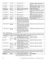
CO Event (If a fire alarm exists and alarms are silenced, a CO event will resound the panel sounder)
– CO Device Activation
• Produces a pulsed audible tone
• Displays a the CO alarm event that indicated the type of device that activated the CO alarm
• Displays
ALARM
in the status banner on the control panel, along with information specific to the device
• Sends a CO alarm message to the LCD display, remote annunciators, history buffer, installed printers, and CRT-2s
• Latches the control panel in CO alarm
• Initiates any Control-By-Event actions
• Activates Special Zone ZFC
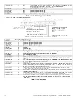
– Responding to a CO event:
1.
To silence only the panel sounder:
Press the
ACKNOWLEDGE
/
SCROLL
DISPLAY
key to silence the panel sounder. The fire panel will send an Acknowledge message to the remote
annunciators, history buffer, installed printers, and CRT-2s.
To silence the panel sounder and any activated outputs that are programmed as silenceable:
Press the
SIGNAL
SILENCE
key. The
SIGNALS
SILENCED
LED will light steady. The control panel sends a Signal Silenced message to the
remote annunciators, history buffer, installed printers, and CRT-2s. Check the alarm message for the location and type of event.
2.
Correct the condition that activated the CO alarm.
3.
Press the
SYSTEM
RESET
key to return the control panel to normal operation.
A “System Normal” message is sent to the LCD display, remote annunciators, history buffer, installed printers, and CRT-2s.
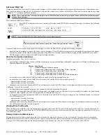
•
Emergency Signaling, Type SM
•
Smoke Control, Smoke Movement
All fires produce smoke, and the movement of smoke will follow the same pattern as the overall air movement within a building, often flowing
away from the fire to unwanted areas. A smoke control system must be able to inhibit the flow of smoke within a building. Elements that cause
the movement of smoke include one or more of the following:
– Stack effect
– Buoyancy of the smoke
– Expansion
– Wind
– Elevator piston effect
– the HVAC system
Principles of Smoke Control
The smoke control system uses a building’s ventilation system to exhaust the fire floor and pressurize surrounding floors. The three major
considerations for smoke control are:
– Smoke containment
– Purging
– Door-opening forces
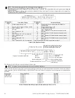
NOTE:
An ACM-24AT or AEM-24AT LED point must be programmed as a dedicated visual indicator of a CO event. This is not required for
display-less systems.
A C T I V E T A M P E R
I N T E N S I V E C A R E U N I T
E A S T E R N W I N G
Z 0 0 4
0 3 : 1 9 P 0 4 1 5 1 2 1 M 1 4 7
Status Banner
Type Code
Custom descriptor for
this device location
Device address
Time and date of trouble
Zone
Extended 12 character
custom label
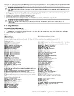
Figure 31 Sample Supervisory Message
A L A R M : C O
I N T E N S I V E C A R E U N I T
E A S T E R N W I N G
Z 0 0 4
0 3 : 1 9 P 0 4 1 5 1 2 2 M 1 4 7
Status Banner
CO Alarm indicator
Custom descriptor for
this device location
Device address
Time and date of trouble
Zone
Extended 12 character
custom label
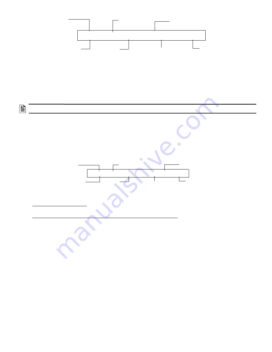
Figure 32 Sample CO Alarm Message


