24
NFS-320 and NFS-320SYS UL Listing Document —
P/N 52745LD:G9 5/19/2022
4 Programming Options
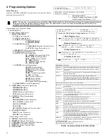
Menu Hierarchy
From the “SYSTEM NORMAL” screen: Press
ENTER
, press
1.
Enter a
password, then press
ENTER
Programming Level: Program Change
1 = PROGRAMMING
Program Change (High Level)
1 =
BASIC PROGRAM
0 = CLR
(Clear Program)
1 = AUTO
(Autoprogram)
2 = POINT
(Point Program)
1 = MODIFY POINT
2 = DELETE POINT
3 = PASSWD
(Password)
* = PROGRAM
(Program Password Level)
# = STATUS
(Status Password Level)
4 = MESSAGE
(All Systems Normal Message)
5 = ZONES
(Zone Programming)
6 = SPL FUNCT
(Special Function)
F0 = PRESIG
(Presignal Delay/PAS)
R0-R9 = REL
(Releasing Zones)
F5-F6 = TIME
(Time Function)
F7 = HOL
(Holiday)
F8 = CODE
(Coding Function)
F9 = PRE-ALARM
7 = SYSTEM
(System Programming)
SIL INH
(Silence Inhibit)
AUTO
(Auto Silence Timer)
VERIFY
(Alarm Verification)
USA TIME
TERM
(Terminal Supervision)
AC DLY
(AC Delay)
LocT
(Terminal Location)
BLINK
(Device Blink)
ST
(SLC Wiring Style)
ACS
(Annunciator Programming)
8 = CHECK PRG
(Check Programming)
2 = NETWORK
(Network Programming)
THRESHOLD CH. A
THRESHOLD CH. B
NODE
(Network Node Number)
STYLE
(Network Wiring Style)
3 = UTILITY
(Utility Programming)
REGION
TBL. REMIND
(Trouble Reminder)
ALA. SCROLL
(Alarm Scroll)
LOCAL CONTROL
IP-ACCESS
DCC MODE
(Display and Control Center)
4 = FLASHSCAN POLL
L1DET
(Loop 1 Detectors)
L1MOD
(Loop 1 Modules)
Status Change (Low Level)
1 = DISABL
(Disable/Enable Point)
2 = SENSITIV
(Detector Sensitivity)
3 = CLR VER
(Clear Alarm Verification Counters)
4 = CLR HIST
(Clear History Buffer)
5 = TIME
(Set System Time and Date)
6 = WALK TEST
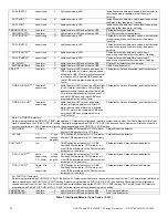
NOTE:
During a local or network Walk Test, activating a Mass Notification device will activate associated special function zones according to
CBE programming and simulate a Mass Notification event. Any network nodes, zones, or devices not participating in Walk Test will not
participate in the simulated Mass Notification event.
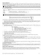
Enter password here
Program Change Level Default = 00000
Status Change Level Default = 11111
ENTER PROG OR STAT PASSWORD, THEN ENTER.
(ESCAPE TO ABORT) _
1 = P R O G R A M M I N G
2 = R E A D S T A T U S E N T R Y
( E S C A P E T O A B O R T )
Choose one of the Program Change selections: 1, 2, 3 or 4
1 Basic Program
options
3 Utility Program
options
4 FlashScan Poll
options
2 Network Program
options
1 = B A S I C P R O G R A M
2 = N E T W O R K
3 - U T I L I T Y
4 = F L A S H S C A N P O L L
0 = C L R 1 = A U T O 2 = P O I N T 3 = P A S S W D 4 = M E S S A G E
5 = Z O N E S 6 = S P L F U N C T 7 = S Y S T E M 8 = C H E C K P R G
T H R E S H O L D C H . A : H , T H R E S H O L D C H . B : H
N O D E :
. 0 0 0 , C L A S S A : Y ,
< E N T E R >
R E G I O N = 0 T B L . R E M I N D = 2 A L A . S C R O L L = N
L O C A L C O N T R O L = 0
F L A S H S C A N
L 1 D E T L 1 M O D
N
Y
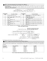
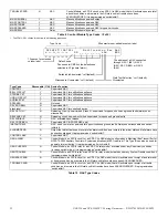
Special Zone
Lets you
F0=
PRESIG
Select a Presignal Delay Timer and select PAS (Positive Alarm Sequence)
F5-F6=
TIME
Specify Time Control functions such as the start time, stop time, or days of
the week
F7=
HOL
Specify up to nine holiday dates. An F7-programmed device activates on the
specified holiday dates
F8=
CODE
Specify one of the following coding function selections: March Time,
Temporal, California, Two-Stage, Two-Stage Canada (3 minute or 5 minute),
Two-Stage Canada Manual, System Sensor Strobes, Gentex Strobes, or
Wheelock Strobes. F8 only takes effect if you program one or more NACs to
F8
F9=
PRE
-
ALARM
Select a Pre-Alar m level: Alert or Action
FA
†
(ZF10*)
Turn on when detector in verification mode. This is a fixed point and is not
programmable
FB
†
(ZF16*)
Turn on if custom drill set to Y and the panel in Drill mode (Alarm Signal On in
Canadian applications).
FC
†
(ZF18*)
Turn on when a CO alarm occurs.
FD
†
(ZF20*)
Turn on when a Mass Notification Alarm occurs (Does not apply for
FirstCommand applications)
FE
†
(ZF21*)
Turn on when a Mass Notification Supervisory occurs
FF
†
(ZF22*)
Turn on when a Mass Notification Trouble occurs
ZF36*
If the local control active LED is on, this special zone will activate
ZF37*
Automatic Alarm Signal Activation Timer will turn on when the first alert stage
has been entered.
ZF38*
Turns on when the panel enters the second (evacuation) stage.
ZF39*
+
Automatic Alarm Signal Timer canceled. Can only be canceled if there is an
ACS button mapped to this zone.
ZF40*
Auto Silence Activation. ZF40 will activate when the auto silence timer has
expired and silenceable outputs on the fire panel have been silenced as a
result. ZF40 will remain active until a system reset, resound, or drill (alarm
signal On for Canadian applications) is performed.
R0-R9=
REL
Program up to ten Releasing Zones, each with a selection for a Delay Timer,
an Abort Switch, a Cross Zone selection, or a Soak Timer
* VeriFire Tools settings.
†
Not field programmable. Used for CBE programming only.
+
Required for stand alone application
Table 3 Summary of Special Function Zones


