134
NFW-50X Manual —
P/N LS10129-001NF-E:C 7/25/2018
Appendix C: NFPA Standard-Specific Requirements
The NFW-50X has been designed for use in commercial, industrial, and institutional applications and meets the requirements for service
under the National Fire Protection Association (NFPA) Standards outlined in this Appendix. The minimum system components required
for compliance with the appropriate NFPA standard are listed below:
NFW-50X
Control Panel
Contains the main control board, cabinet (backbox and door), main power supply transformer and power supply.
Batteries
Refer to “Power Supply Calculations” on page 125, for Standby Power Requirements.
Initiating Devices
Connected to one of the control panel's Initiating Device Circuits.
Notification Appliances
Connected to the control panel's Notification Appliance Circuits via a control module.
The following additional equipment is needed for compliance with the NFPA 72 standards listed below:
NFPA 72 NATIONAL FIRE ALARM STANDARDS FOR:
NFPA 72 Central Station Service (Protected Premises Unit) or Remote Station Service
Onboard Digital Alarm Communicator Transmitter for connection to a compatible listed Central Station DACR or Protected
Premises Receiving Unit. This unit must be installed as outlined in “Components” on page 15.
OR
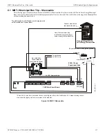
4XTM Transmitter Module for connection to the RS82 Remote Station Receiver. See Figure C.2, “Remote Station Connection
Using 4XTM Module,” on page 135, for installation instructions for this unit.
NFPA 72 Auxiliary Fire Alarm System
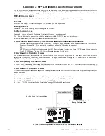
4XTM Transmitter Module for connection to a compatible listed Local Energy Municipal Box. This unit must be installed as illustrated
in the section titled “4XTM Transmitter Module Installation” on page 29 and as outlined in Figure C.1, “Municipal Box Connected to
4XTM Transmitter Module” on page 134.
NFPA 72 Proprietary Fire Alarm System
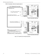
NFW-50X Alarm, Trouble and Supervisory contacts connected to Transmitter(s). See Figure C.3, “Proprietary Protective Signaling Sys-
tem,” on page 136, for installation instructions for this unit.
NFPA 72 Auxiliary Fire Alarm System
All connections are power-limited and supervised. This application is not suitable for separate transmission of sprinkler supervisory or
trouble conditions.
Notes:
1.
3 ohms maximum loop resistance allowed for wiring from control panel to Municipal Box.
2.
Cut JP3 on the NFW-50X main circuit board to supervise placement of 4XTM module and circuit.
3.
Cut JP2 on the NFW-50X main circuit board to enable FACP Supervisory relay.
4.
Refer to “4XTM Transmitter Module Installation” on page 29 for detailed information.
FIRE
Gamewell Model M34-56 Local
Energy Municipal Box
Polarities shown in alarm condition
+
Nonpower-limited
Municipal Box Circuit
+
-
-
4XTM
Figure C.1 Municipal Box Connected to 4XTM Transmitter Module

