background image

NFN Gateway Overview

Agency Listings

14

NFN Gateway Installation & Operation Manual - P/N: 52306:Rev: D  06/01/07

1.4  Agency Listings

This product is intended to be installed in accordance with the Local Authority Having Jurisdiction 
(LAHJ) and has been investigated to, and found to be in compliance with the following standards 
and documents.  Before proceeding, the installer should be familiar with them too.

Underwriters Laboratories U.S. Documents

UL-294: Access Control System Units, Fifth Edition.

UL-864: Control Units for Fire Protective Signaling Systems, Ninth Edition.

UL-1076: Proprietary Burglar Alarm Units and Systems, Fifth Edition.

Underwriters Laboratories Canada Documents

CAN/ULC-S527-99: Standard for Control Units for Fire Alarm Systems.

National Fire Protection Association Standards

NFPA 70: National Electrical Code.

NFPA 72: Installation, Maintenance, and Use of Protective Signaling Systems.

1.4.1  Environmental Requirements

This product must be installed in the following environmental conditions:

Temperature range of 0°C to 49°C (32°F - 120°F).

93% humidity non-condensing at 30°C (86°F).

NOTE:

ONYXWorks

®


systems work with products that have been certified to comply with the 

requirements in the Standard for Control Units and Accessories for Fire Alarm Systems, UL 864 
9th Edition, as well as products that have not received UL 864 9th Edition certification.  Operation 
of a UL 864 9th Edition compliant system together with products not tested for UL 864 9th Edition 
has not been UL evaluated.  Such operation requires the approval of the local Authority Having 
Jurisdiction (AHJ).

!

WARNING: Installation

Improper installation, maintenance, and lack of routine testing could result in system malfunction.

Summary of Contents for NOTIFIER ONYXWorks NFN Gateway

Page 1: ...ONYXWorks NFN Gateway Embedded Installation Operation Manual Document 52306 06 01 07 Rev D P N 52306 D ECN 06 053 ...

Page 2: ...of detec tor may not provide adequate warning of a fire Smoke detectors cannot be expected to provide adequate warning of fires caused by arson children playing with matches especially in bedrooms smoking in bed and violent explosions caused by escap ing gas improper storage of flammable materials etc Heat detectors do not sense particles of combustion and alarm only when heat on their sensors inc...

Page 3: ...ll electronic assemblies prior to any drilling filing reaming or punching of the enclosure When possible make all cable entries from the sides or rear Before making modifications verify that they will not interfere with battery transformer and printed circuit board location Do not tighten screw terminals more than 9 in lbs Over tightening may damage threads resulting in reduced terminal contact pr...

Page 4: ...urate If you have any comments you can email us Please include the following information Product name and version number if applicable Manual page number Your comment Send email messages to FireSystems TechPubs honeywell com Please note this email address is for documentation feedback only If you have any technical issues please contact Technical Services ...

Page 5: ...ation Diagram 21 2 5 Network Communication Module Installation 22 Figure 2 5 NCM W F PC Board Installation Document 22 Figure 2 6 NCM W F Power Connection 22 2 6 NFN Gateway Power Connection 23 Table 2 1 Power Supply Specifications 23 Figure 2 7 NFN Gateway Power Connection 23 2 7 NFN Gateway Cable Connections 24 2 7 1 IP Cable Connections 24 Figure 2 8 IP Cable Connection 24 2 7 2 Gateway Network...

Page 6: ...sword Window 37 Section 4 NFN Config Tool Reference Information 39 4 1 NFN Config Tool Description 39 4 2 Property Value Field Descriptions 39 Figure 4 1 NFN Config Tool Field Descriptions 39 4 2 1 GATEWAY SETTINGS Fields 40 4 2 2 IP Configuration Fields 40 Figure 4 2 NFN Config Tool IP Configuration Property Value Field Descriptions 40 4 2 3 SNTP Configuration Fields 40 Figure 4 3 NFN Config Tool...

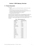
Page 7: ...on resides on a PC board assembly that is installed inside a CAB 3 4 series cabinet It communicates with any ONYXWorks Workstation software application or FIRSTVISION on the system via an IP connection over Ethernet networks The NFN Gateway acts like any other node on a NFN network and is compatible with the following node types An indicates panels that support using a USB or serial cable for the ...

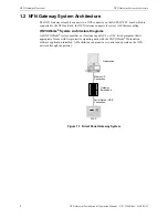
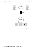
Page 8: ...nects to system via Ethernet cabling ONYXWorks System Architecture Diagrams An ONYXWorks system must have at least one capable UL or ULC listed computer that is appropriate for use with fire protective signaling units with the ONYXWorks Workstation software application installed A Workstation can monitor or control node points on the NFN network through the gateway Figure 1 1 Direct Panel Gateway ...

Page 9: ...re NFN Gateway Overview 9 NFN Gateway Installation Operation Manual P N 52306 Rev D 06 01 07 Figure 1 2 ONYXWorks System Example 1 A Single NFN Network FACP FACP NFN Network IP Network Gateway Embedded FACP Workstation Workstation ...

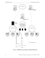
Page 10: ...ONYXWorks System Example 2 Multiple NFN Networks FACP FACP NFN Network IP Network Gateway Embedded FACP Workstation Gateway PC Workstation FACP FACP NFN Network FACP Workstation Echelon Gateway Style 4 6 or 7 Echelon Network Wire or Fiber ULC Style DCLA DCLB and DCLR NION NION NION Voice Paging Equipment NOTIFY PAA ACT 2 XPIQ Speakers ...

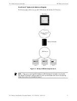
Page 11: ...tes a possible NFN network that includes NFN Gateway Figure 1 4 Example NFN Gateway Network FIRSTVISION FACP FACP NFN Network Ethernet TCP IP Network Gateway Embedded FACP NOTE If if you are connecting NFN Gateway to a NFN Gateway PC and plan on running the ONYXWorks Workstation software application also the Workstation must be set to Supervising Station Mode refer to the Workstation manual ...

Page 12: ...on ONYXWorks clients in the most basic system can co exist on one computer For more powerful systems multiple computers can be networked together over the IP network running multiple instances of the Workstation software application or other clients and gateways If the Workstation or gateway are sharing on premises communications equipment the shared equipment shall be listed for the purpose Liste...

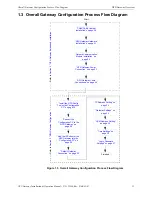
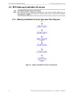
Page 13: ... on page 22 NFN Gateway Power Connection on page 23 NFN Gateway Cable Connections on page 24 Install the NFN Config Tool on the Configuration PC on page 30 Connect the Configuration PC to the NFN Gateway on page 30 Add the IP Subnet of the NFN Gateway into the Configuration PC on page 32 Refer to Section 3 NFN Gateway Configuration Start Default Gateway Connection on page 33 Finished Gateway Setti...

Page 14: ...onal Fire Protection Association Standards NFPA 70 National Electrical Code NFPA 72 Installation Maintenance and Use of Protective Signaling Systems 1 4 1 Environmental Requirements This product must be installed in the following environmental conditions Temperature range of 0 C to 49 C 32 F 120 F 93 humidity non condensing at 30 C 86 F NOTE ONYXWorks systems work with products that have been cert...

Page 15: ...Tool P N 53038 FIRSTVISION Configuration Tool P N 53035 FIRSTVISION Installation and Operation Manual P N 53034 NOTE The contents of this manual are important and must be kept in close proximity of the installed equipment If building ownership is changed this manual including all other testing and maintenance information must also be passed to the current owner of the facility A copy of this manua...

Page 16: ...NFN Gateway Overview Related Documentation 16 NFN Gateway Installation Operation Manual P N 52306 Rev D 06 01 07 ...

Page 17: ...NFN Gateway PC board to an NCM W F board NUP to 24VDC power cable P N 75583 used for supply power to the NCM W F board NFN Config Tool Network Components RJ45 to RJ45 standard Ethernet network cable customer s internet or intranet connection to PNET 1 surge suppressor supplied by customer ONYXWorks Workstation v3 0 or above or FIRSTVISION v1 4 or above sold separately NFN network version 5 0 or ab...

Page 18: ...y Installations NFN Gateways should be installed and configured one at a time because all NFN Gateway use the same predefined IP address and node number therefore when you go to configure the one gateway it can be found to configure CAB3 CAB4 Cabinet Installation on page 20 NFN Gateway Hardware Installation on page 21 NetworkCommunication Module Installation on page 22 NFN Gateway Power Connection...

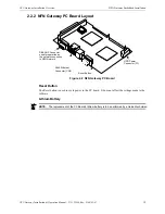
Page 19: ...eway PC Board Reset Button The Reset button is used to cycle power to the PC board It does not affect the settings made to the software Lithium Battery DB9 NUP Connector used for operation as the network connection to NFN Network RJ45 Ethernet Connector CN2 HDD Power Connector P1 Reset Button NOTE The replacement of the PC Board s lithium battery is to be performed by a trained technician ...

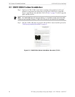
Page 20: ...ple chassis including the CHS M2 CHS M3 CHS 4 CHS 4L CHS 4N CHS BH CHS PS CA 1 and CA 2 Note CAB 4 series backboxes and doors are sold separately 2 Before You Begin The option of mounting doors in either a left right hand configuration will aid in installation and service when two control panels are mounted in a confined area or side by side as shown In this manner the doors can be opened barn doo...

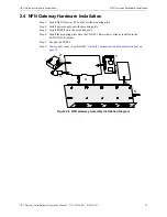
Page 21: ...onto the mounting plate Step 2 Install power supply onto the mounting plate Step 3 Install PNET 1 onto the mounting plate Step 4 Install the mounting plate onto the CHS 4L chassis that is already installed in the CAB3 CAB 4 cabinet Step 5 Ground the PNET 1 Step 6 You are now ready to perform the Network Communication Module Installation on page 22 Figure 2 4 NFN Gateway Assembly Installation Diagr...

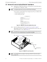
Page 22: ...ns Operation of the NCM W NCM F with products not tested for UL 864 9th Edition has not been evaluated and may not comply with NFPA 72 and or the latest edition of UL 864 These applications will require the approval of the local Authority Having Jurisdiction AHJ AM2020 AFP1010 MIB NAM 232 2 Product Overview The Network Communications Module NCM provides a means for connecting specific Notifier fir...

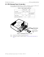
Page 23: ...Power Connection Step 1 Connect the power supply to the gateway Figure 2 7 Step 2 After the power supply is connected perform NFN Gateway Cable Connections on page 24 Table 2 1 Power Supply Specifications TYPICAL MIN MAX Input Voltage 24VDC 19VDC 29V Input Current 24VDC 360 mA without NCM 450 mA with NCM Output Voltage 5V 4 8V 5 2V Output Current 24VDC 1 2 A 5VDC Output Earth 24VDC Input 24VDC REF...

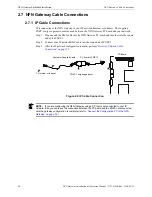
Page 24: ... the other into the square end of the PNET 1 Step 2 Connect your IP network RJ45 cable into the round end of PNET 1 Step 3 After the IP network configuration is made perform Gateway Network Cable Connection on page 25 Figure 2 8 IP Cable Connection PNET 1 surge suppressor PC board to PNET 1 To Internet or Intranet PC Board Customer Supplied Cable NOTE If you are configuring the NFN Gateway using a...

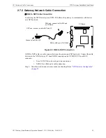
Page 25: ...o NUP Connection A DB9 to NUP cable is used to connect between the gateway and NFN network Connect the cable between to the NFN Gateway PC board s DB9 connector and a NCM W F PC board NUP connector Use a NCM W for a twisted pair wire connection NCM F for a fiber optic cable connection Step 4 After these cable connection are made you should perform NFN Gateway Configuration on page 29 Connect to an...

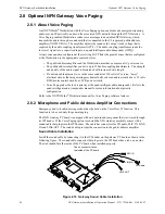
Page 26: ...ent to or in the same conduit as 120 volts AC service noisy electrical circuits that are powering mechanical bells or horns audio circuits above 25 volts RMS motor control circuits or SCR power circuits Voice Paging takes the lowest priority at the quad intelligent audio transponder Refer to the quad intelligent audio transponder manual for more information about priority configuration Refer to th...

Page 27: ...USIC and GND terminals on the public address amplifier Step 3 Use 18AWG 12AWG twisted pair cable to connect the COM and 25V terminals on the public address amplifier to the AUDIO IN terminals on the audio coupling transformer Step 4 Connect the public address amplifier AC power cord to the primary AC power source Figure 2 11 Public Address Amplifier Connections to Gateway Sound Cable NOTE The NOTI...

Page 28: ...NFN Gateway Embedded Installation Optional NFN Gateway Voice Paging 28 NFN Gateway Installation Operation Manual P N 52306 Rev D 06 01 07 ...

Page 29: ... and node number NOTE ONYXWorks system v3 0 or later or FIRSTVISION v1 4 or later are required when installing this NFN Gateway From Gateway Installation Process Flow Diagram on page 18 Install the NFN Config Tool on the Configuration PC on page 30 Connect the Configuration PC to the NFN Gateway on page 30 Add the IP Subnet of the NFN Gateway into the Configuration PC on page 32 Default Gateway Co...

Page 30: ...ct the Configuration PC to the NFN Gateway Use one of the following methods to connect the Configuration PC to the NFN Gateway If the Configuration PC is on your IP network then you already have connected it to the NFN Gateway if you performed the IP Cable Connections on page 24 Therefore you need to Add the IP Subnet of the NFN Gateway into the Configuration PC on page 32 If you are going to use ...

Page 31: ... Gateway into the Configuration PC on page 32 Cross Over Cable Specifications This cross over cable will be directly connected between the Configuration PC network card s RJ45 connector and the NFN Gateway PC board s RJ45 connector The cross over cable can be purchased or you can make one Please use the following information for the correct pinout requirements for each end of the cable EIA TIA wir...

Page 32: ...nternet Protocol TCP IP entry and then click on it Step 4 Click on the Properties button The Internet Protocol TCP IP Properties window displays Step 5 Select the Advanced button The Advanced TCP IP Settings window displays Step 6 Click on the Add button The TCP IP Address window displays Figure 3 3 TCP IP Address Window Step 7 Type in a Configuration PC IP address value for the following IP addre...

Page 33: ...efault gateway from the list of choices The NFN Config Tool auto detects and loads the default gateway default node number is 240 Panels connected to the gateway are displayed Status messages are displayed at the bottom the window Step 3 The NFN Gateway has a default IP address and you need to change it so it will be added onto your IP network so perform the NFN Gateway Configuration Procedure on ...

Page 34: ...t to Gateway Property and then type in the address the router will be using on your IP network b Press the keyboard enter key Step 5 Change the default NFN Gateway IP address so it will be added onto your IP network Figure 3 6 Gateway IP Configuration a Click on the IP Configuration entry in the Nodes column b Click on the Value field adjacent to IP Address Property and then type in the address th...

Page 35: ...he default password is 00000000 eight zeros Step 3 Select the highest level entry in the Nodes list column hierarchy The gateway s Property and Value information displays Step 4 Click in the Value field adjacent to Mode Property to display the list of choices and then select the desired mode Figure 3 7 Gateway Mode Setting Step 5 Now you need to perform NCM Address Setting NCM Address Setting Step...

Page 36: ...the Value field adjacent to SNTP Server Address Property and then type in the address of the server Step 4 Press the keyboard enter key Time Zone Configuration Step 5 Click on the Time Zone Configuration entry in the Nodes column Figure 3 11 Gateway Time Settings Step 6 Click in the Value field adjacent to GMT Minute Offset Property type in the entry and then press the keyboard enter key The GMT M...

Page 37: ...me the gateway is started the factory default password is used 00000000 eight zeros after the initial configuration it is highly recommended that you change the password Step 1 Select Tools Set Gateway Password The Gateway Login change password window displays Figure 3 12 Gateway Login Change Password Window Step 2 Type in the current password in the Password field Passwords are case sensitive Alp...

Page 38: ...NFN Gateway Configuration NFN Gateway Configuration Procedure 38 NFN Gateway Installation Operation Manual P N 52306 Rev D 06 01 07 ...

Page 39: ...VALUE columns display information about the selection made in the Nodes list Property fields that are preceded with an asterisk mean the Value adjacent to it can be modified in some way 4 2 Property Value Field Descriptions The NFN Config Tool window displays configuration information about the gateway and the NFN network the gateway is monitoring When logged into the gateway using a password you ...

Page 40: ... the audio option if installed Channel A and Channel B Threshold Are set according to the determined amount of network noise that is present in the network High is used when the most noise is present and filter that noise accordingly Style 7 If set to True Style 7 is used if set to False Style 4 is used COMM Port Is used to specify which port the NFN Gateway uses to communicate with NCM 4 2 2 IP C...

Page 41: ... field Time Zone Reference Is used to set the time zone standard The choices are US Standard When selected the DST Begin and DST End settings are automatically populated with the appropriate settings EU Standard When selected the DST Begin and DST End settings are automatically populated with the appropriate settings Custom If selected requires that DST Begin and DST End settings be made DST Begin...

Page 42: ...iptions PANEL PROPERTIES Node Is used to change the NFN network address of the panel VERSIONS If the NCM Version field is displayed in red then the version doesn t match the Local Node entry NOTE The NCM version for panel must match the NCM version displayed in the Local Node entry When it does not match the non matching version is displayed as a red entry Contact Technical Services for assistance...

Page 43: ...s that will be available and displayed when the NFN Config Tool s Address field down arrow is clicked Refresh Nodes List Used to ping the nodes connected to the current gateway and display their information Node Table Displays all the nodes connected to the gateway and their respective version information Connected Clients Used to display a window which lists the clients that are connected to the ...

Page 44: ...click options are also available for the selection made in the Nodes list column Delete Node Is used to remove a node from the gateway The Node must be offline before it can be deleted Auto Detect Nodes Is used to force the gateway to detect nodes on the NFN network The gateway searches for all online nodes on the NFN network Set Gateway Password Refer to Login Password Settings on page 37 4 3 4 H...

Page 45: ...40 assembly 17 Assembly Installation Diagram 21 configuration 29 Configuration Procedure 34 default IP Address 32 Hardware Installation 21 IP cable connection 24 mode 35 multiple 29 Optional Voice Paging 26 Power Connection 23 Power supply part number 17 product description 7 Required Equipment 17 Subnet Mask Address 32 Gateway Config Tool field descriptions 39 Gateway Installation Overview 18 Gat...

Page 46: ...mber 17 output current 23 output voltage 23 Proprietary Supervising Station 12 Public Address Amplifier Connection 27 R Reboot Gateway 43 Refresh Gateway List 43 Refresh Nodes List 43 S Set Gateway Password 44 SNPT Server Address 40 Sound Cable 26 Style 7 40 Subnet Mask 40 SUP 40 T Time Zone Reference 41 Custom 41 EU Standard 41 US Standard 41 Tools menu descriptions 44 Trouble Reminder 40 twisted...

Page 47: ...if there is a failure to maintain the products and systems in which they operate in a proper and workable manner In case of defect secure a Return Material Authorization form from our Return Authorization Department This writing constitutes the only warranty made by Honeywell International Inc with respect to its products Honeywell International Inc does not represent that its products will preven...

Page 48: ...World Headquarters 12 Clintonville Road Northford CT 06472 1610 USA 203 484 7161 fax 203 484 7118 www notifier com ...

Reviews: