RP-2001 Series Manual —
P/N 52985:D5 1/26/2017
51
Master Programming Level
Programming
3.5 Master Programming Level
When the Master Program Level password is entered, the control panel will enter user
Programming mode. In this mode, the piezo sounder remains off, the trouble relay is activated and
the system Trouble indicator flashes until Programming mode is exited. The following display will
appear:
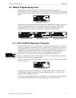
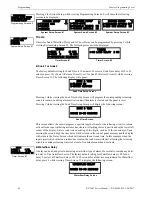
The down arrow which appears in the display indicates that additional programming choices can be
viewed by pressing the down arrow key on the keypad. If a down and up arrow appear in the
display, pressing the ‘down’ arrow key will display the subsequent Programming Screens as
illustrated below while pressing the ‘up’ arrow key will display the previous screen.
3.5.1 FACP CONFIG (Application Templates)
For a detailed description of each Template, refer to “FACP Configuration Templates” on page 96.
The FACP Configuration option allows the user to program the FACP with one of seven factory
preprogrammed templates or one custom template which can be programmed by the user. The
templates have been provided to allow the user to quickly program the panel with typical job-site
configurations. The user may choose to select one of the templates or bypass this option,
proceeding to the next sections which detail customized programming of the FACP.
A factory template may be chosen and later changed to better fit a site requirement. The changed
template can be saved as the one custom template.
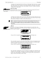
Pressing
1
, while viewing Programming Screen #1, will select the
FACP Config
option and display
the following screen:
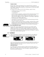
Pressing the down arrow key will display screens for additional Templates 1 through 7 and the
Custom Template. During initialization of the panel following power-up or reset, the selected
Template will be displayed by the LCD.
To select a pre-programmed template, press the number key corresponding to the desired template.
Note that the factory templates may pre-set most programmable features of the FACP.
PROGRAMMING
1=FACP CONFIG T7
2=INPUT ZONES
3=OUTPUT CIRCUITS
Programming Screen #1
PROGRAMMING
1=CROSS INPUT ZONES
2=ON-BOARD RELAYS
3=SYSTEM SETUP
PROGRAMMING
1=ANN-BUS
2=HISTORY 256 EVENTS
3=WALKTEST
Programming Screen #2
Programming Screen #3
PROGRAMMING
1=CLEAR PROGRAM
2=PASSWORD CHANGE
Programming Screen #4
PROGRAMMING
1=FACP CONFIG USER
2=INPUT ZONES
3=OUTPUT CIRCUITS
Programming Screen #1
FACP CONFIG
1=TEMPLATE 1
2=TEMPLATE 2
3=TEMPLATE 3
FACP Config Screen #1


