94
RP-2001 Series Manual —
P/N 52985:D5 1/26/2017
Circuit Mapping and Cross-Zoning
Input-to-Output Circuit Mapping and Cross-Zone Operation
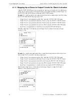
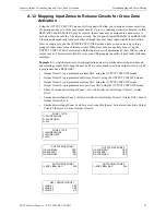
Example 4:
A dual hazard, cross-zoned application using four input zones and two releasing output
circuits. Input Zones 1 and 2 are cross-zoned to activate Output Circuit 2, which is programmed as
RELEASE 1. Input Zones 3 and 4 are cross-zoned to activate Output Circuit 3, which is
programmed as a RELEASE 2.
•
Output Circuit 1 is programmed as alarm NAC using the
OUTPUT CIRCUITS
menus.
•
Output Circuit 2 is programmed as Release Circuit 1 using the
OUTPUT CIRCUITS
menus.
•
Output Circuit 3 is programmed as Release Circuit 2 using the
OUTPUT CIRCUITS
menus
•
Output Circuit 4 is programmed as supervisory NAC using the
OUTPUT CIRCUITS
menus.
•
Any of smoke detector Input Zones 1 through 4 will directly activate Output Circuit 1 (Alarm
NAC) but not Output Circuits 2, 3 or 4.
•
Smoke detector Input Zones 1 and 2 are cross-zoned (both must be in alarm) to activate Output
Circuit 2 (Release 1) but not Output Circuits 3 or 4.
•
Smoke detector Input Zones 3 and 4 are cross-zoned (both must be in alarm) to activate Output
Circuit 3 (Release 2) but not Output Circuits 2 or 4.
ZONE 1 TYPE
1=2-WIRE SMOKE
2=2-WIRE HEAT
3=N/A
OUTPUT MAP ZONE 1
1=ALARM NAC YES
2=RELEASE 1 YES
3=RELEASE 2 NO
OUTPUT MAP ZONE 1
1=SUPV BELL NAC N/A
REL 1 CROSS GROUP 1
1=ZONE 1 YES
2=ZONE 2 YES
3=ZONE 3 NO
OUTPUT MAP ZONE 2
1=SUPV BELL NAC N/A
ZONE 2 TYPE
1=2-WIRE SMOKE
2=2-WIRE HEAT
3=N/A
OUTPUT MAP ZONE 2
1=ALARM NAC YES
2=RELEASE 1 YES
3=RELEASE 2 NO
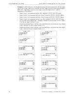
ZONE 3 TYPE
1=2-WIRE SMOKE
2=2-WIRE HEAT
3=N/A
ZONE 4 TYPE
1=2-WIRE SMOKE
2=2-WIRE HEAT
3=N/A
OUTPUT MAP ZONE 3
1=ALARM NAC YES
2=RELEASE 1 NO
3=RELEASE 2 YES
OUTPUT MAP ZONE 3
1=SUPV BELL NAC N/A
OUTPUT MAP ZONE 4
1=SUPV BELL NAC N/A
OUTPUT MAP ZONE 4
1=ALARM NAC YES
2=RELEASE 1 NO
3=RELEASE 2 YES
REL 2 CROSS GROUP 1
1=ZONE 1 NO
2=ZONE 2 NO
3=ZONE 3 YES
REL 2 CROSS GROUP 1
1=ZONE 4 YES
2=ZONE 5 NO
3=ZONE 6 NO

