S-885.1-SKBR3N-ENG Rev. A.1 06/2017
SKBR3N
Relay card for Smart 3 and Smart S detectors
INTRODUCTION
The three-relay card for SMART3/SMARTS gas
detectors allows the detector to be provided with tension
free changeover contacts.
-The first output is to be associated to the Fault and
Watch-dog alarm
-The second output can be associated to the first or
second alarm threshold
-The third output can be associated to the second or third
alarm threshold.
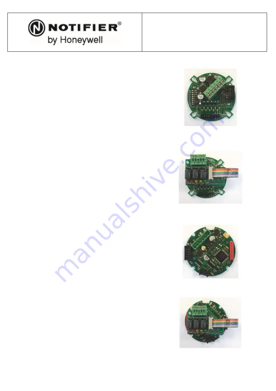
The card comes complete with a flat cable and
connector to be easily plugged on the detector's mother
board.
Note: once used with the Smart S detector, the function
of the relays can be modified by the detectors operating
menu
TECHNICAL SPECIFICATIONS
CONTACTS RATING:
24Vdc-1A
OPERATION VOLTAGE:
from 10,2Vdc to 28Vdc
Before connecting the relay card, please make sure the
detector's operation voltage is within the values here
above.
MOUNTING
Verify the detector has been disconnected before
mounting the ST.S/3REL+
Insert the supports into the holes on the PCB, as per the
drawing on page 2.
Insert the female connector at the edge of the flat cable
into the male connector on the PCB of the detector.
Beware that the black triangle on the female connector
(corresponding to pin one) is facing towards the internal
part of the PCB.
Tighten the card to the supports with the screws the
relay-card kit is equipped with.
Once the card has been properly mounted the terminal
block shall be faced towards the upper part of the
detector, i.e. towards the detector terminal block.
The detector can now be wired, connected and powered
on.
IMPORTANT NOTICE: for the SMART3G’s series
detectors, in order to properly activate the ST.S3REL+
relays card it is mandatory to open the jumper JP5-6 on
the detector’s main PCB (refer to the SMART3G's
detector manual).
SCHEDA SMART3G
MONTAGGIO SU RILEVATORE SMART3G
SCHEDA SMART “S”
MONTAGGIO SU RILEVATORE SMART “S


