
VGN
S-894.1-VGNPARK-ITA/ENG REV. A.1 03/2006
Pag. 5 di 6
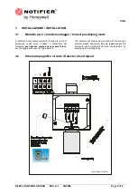
3.3
Collegamento / Connection
Verificare che nella confezione ci siano tutte le parti
componenti.
Per il collegamento del sensore con l'unità di
elaborazione e alimentazione si raccomanda l'uso di
cavo schermato. La sezione del cavo da utilizzare
dipende dalla distanza del rilevatore dalla centrale:
-per distanze inferiori a
100mt.
si usino cavi con
sezione di 0.75 mm
2
;
-per distanze comprese fra
100 e 200 mt
si usino cavi
con sezione di 1.0 mm
2
;
-per distanze comprese fra
200 e 300mt
si usino cavi
con sezione di 1.5 mm
2
.
Nel caso vi siano giunzioni nel cavo di collegamento,
assicurarsi che vi sia continuità anche sulla
schermatura dei cavi.
Ricordarsi che la schermatura deve essere collegata a
terra unicamente dal lato unità di controllo o gruppo di
alimentazione, mentre non dovrà mai essere collegata
sui rilevatori.
Assicurarsi che la realizzazione di giunzioni sui cavi di
alimentazione mediante dispositivi di serraggio o a
crimpare, sia eseguito a regola d’arte con capicorda e/o
morsetti che nel tempo non si ossidino o allentino. E’
sempre preferibile eseguire giunzioni saldate.
Il rilevatore “VGN” può essere collegato a centrali di tipo
analogico (4-20 mA) con indicazione proporzionale
della concentrazione di gas in ambiente.
Please check the carton box comprises all of the
components.
Wiring between the detector and the control panel
should be carried out with shielded cables. Wires'
cross section depends on the distance between the
control panel and the detector:
-for a distance up to
m 100
we advice a 3 core wire
with a cross section of 0.75 mm
2
;
-for a distance between
m 100 and 200
we
recommend 3x1.0 mm
2
;
-for a distance between
m 200 and 300
we
recommend 3 x 1.5 mm
2
.
Should any junctions be necessary on the wires,
please make sure there is no interruption on the shield.
Please remember that the shield should be connected
to the ground from the control panel side only. Also
remember never connect the shield to the connectors
Ensure the wire connections, either clutching or
crimping type, are duly carried out with terminals that
do not oxidise or loosen. Better of all would be to
solder them. The “VGN” gas detectors are designed to
be connected to any analogic control unit (4-20 mA)
when panels have an LC display for the proportional
readout of the concentration.
4
COLLAUDO E USO / TESTING AND WORKING OPERATION
4.1
Accensione /
Power ON
Assicurarsi che i collegamenti siano stati realizzati nel
migliore dei modi.
Alimentare la centrale alla quale è collegato il rilevatore.
La centrale stessa permettere al rilevatore di scaldarsi
per raggiungere le condizioni ottimali di impiego. Al
momento dell’ accensione sono necessari 2 minuti circa
prima che la corrente erogata abbia un valore
attendibile. Trascorso tale periodo di tempo la corrente
erogata dal rilevatore deve essere di 4,0 +/- 0,2 mA, in
caso contrario è necessario aspettare 2 ore circa ed
effettuare la taratura dei valori di Zero e 4 mA.
Make sure all connections have been correctly
performed.
Power on the control panel the detectors are
connected to. The control panel will allow the detector
performing a warm-up phase to reach the optimal
working conditions. This phase will require nearly 2
minutes to be performed. After this time interval the
current from the detector must be 4,0 +/- 0,2 mA.
Should not this value be attained it is necessary to wait
for 2 hours and perform the Zero and 4 mA calibration.
5
USO / USE
Il rivelatore funziona automaticamente e
autonomamente pertanto non è richiesto alcun
contributo da parte del suo utilizzatore.
The detector works autonomously and automatically.
Once duly connected no further operations are
required, apart from periodical testing.
6
MANUTENZIONE / MAINTENANCE
6.1
Operazioni di manutenzione preventiva / Preventive maintenance routines
I rivelatori della serie VGN prevedono la possibilità della
taratura in campo dei parametri di Zero, Span (risposta
in gas) e dell’uscita 4-20 mA tramite appunto la tastiera
di calibrazione portatile. E’ possibile modificare i
VGN gas detectors offer a field adjustment for the
Zero, Span (response to gas) and 4-20mA
parameters.
By operating with the portable keypad, pressing


