background image

PRODUCT DATA

68- 0173- 3

® U.S. Registered Trademark
Copyright © 2001 Honeywell •  All Rights Reserved 

Perfect Climate Comfort Center™

Control System

GENERAL

This document contains information on the Perfect Climate 
Comfort Center™ Control System including components and 
accessories. Some components and accessories include the 
PC8900A Control Panel, W8900A-C Remote Module, C7189A 
Remote Indoor Sensor, C7089A Outdoor Sensor, C7100A 
Discharge Air Sensor, CO2 Monitor, CM8900A Communication 
Module, and W8735B Telephone Access Module.

The Comfort Center control system provides 24 Vac energy 
saving control for a heating and cooling system, while 
providing reliable and precise temperature, ventilation and 
humidity control.

FEATURES

The PC8900A mounts in the living space and accurately 
measures and controls room temperature and humidity.

Only four wires required for installation.

Large, continuously lit LCD.

Seven-day (auto copy) programming.

Simultaneous display of heat and cool setpoints.

Keyboard lockout protection available.

No batteries required, indefinite program retention.

Circulation fan setting improves indoor air quality.

Field configurable for:

Automatic or manual changeover.

°F or °C display.

12- or 24-hour clock.

Adaptive Intelligent Recovery™ control or 
conventional recovery.

Humidity control in heating or cooling.

Outdoor, remote, and discharge temperature 
sensors available.

Fan overrun in cooling.

Ventilation control.

The W8900A-C mounts near the equipment. The 
PC8900A, heating, cooling, ventilation and 
dehumidification equipment and all additional sensors 
are wired to the W8900A-C.

Compatible with most 24 Vac Systems.

Remote sensor, discharge sensor, outdoor sensor and 
CO

2

 monitor available.

Optional remote communications available.

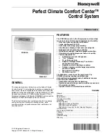
PC8900A

W8900A-C

Contents

General .............................................................................

1

Features ...........................................................................

1

Specifications ...................................................................

2

Ordering Information  ........................................................

2

Installation ........................................................................

5

Wiring Diagrams  ...............................................................

9

W8900A,C Hookup Diagrams ......................................

9

W8900B Hookup Diagrams  ......................................... 14
W8900A,B,C Humidity Control Hookup Diagrams ....... 18

Installer Setup  .................................................................. 24
Programming PC8900A .................................................... 27
Checkout .......................................................................... 33
Operation .......................................................................... 34
Troubleshooting ................................................................ 40
Glossary ........................................................................... 44

Summary of Contents for PC8900A

Page 1: ...ing Simultaneous display of heat and cool setpoints Keyboard lockout protection available No batteries required indefinite program retention Circulation fan setting improves indoor air quality Field configurable for Automatic or manual changeover F or C display 12 or 24 hour clock Adaptive Intelligent Recovery control or conventional recovery Humidity control in heating or cooling Outdoor remote a...

Page 2: ...ss Module Used for remote communication 202689A Mounting Plate Accessory Used when C7189A Remote Indoor Sensor cannot cover wall marks from old thermostat 205224A Wall Cover Plate Used when PC8900A Control Panel cannot cover wall marks from old thermostat 32007496 001 Replacement Door Used for PC8900A Control Panel Dimensions 205224A See Fig 2 C7089A See Fig 3 C7100A See Fig 4 C7189A See Fig 5 PC8...

Page 3: ...vated Input Ratings 20 to 30 Vac 50 60 Hz Heat Pump Failure Input L Terminal on W8900B Models 24 Vac load 50 60 Hz 0 3 VA load CO2 Monitor Input CO2 Terminal on all W8900A C Models 24 Vac load 50 60 Hz 0 3 VA load Output Ratings Humidity Control Output Relay 50 VA at 24 Vac Ventilation W1 W2 Y1 Y2 E G O B AUX Y1 W1 a 1 5A running 3 5A inrush at 200 000 cycles 30 Vac b 1 5A running 7 5A inrush at 1...

Page 4: ... Dimensions for C7100A Discharge Air Sensor in in mm Fig 5 Dimensions for C7189A Remote Indoor Sensor in in mm M7513 3 1 4 83 8 1 2 216 7 8 22 7 8 22 6 152 M4488 1 1 2 38 3 4 19 13 1 4 336 1 3 16 30 1 3 16 30 1 13 16 46 1 13 16 46 M4461 M4465 4 5 8 117 4 5 8 117 2 3 4 70 2 3 4 70 1 1 8 29 FRONT VIEW SIDE VIEW FRONT VIEW COVER OFF 3 1 4 83 ...

Page 5: ...en Installing this Product 1 Read these instructions carefully Failure to follow instructions can damage the product or cause a hazardous condition 2 Check the ratings on the product to make sure the product is suitable for your application 3 Installer must be a trained experienced service technician 4 After completing installation use these instructions to check out product operation M6356 3 1 4 ...

Page 6: ...7 32 in holes Gently tap anchors provided into drilled holes until flush with the wall 5 Reposition the W8900A C over the holes Loosely insert the four mounting screws included into the holes Fig 9 Mounting W8900A C Remote Module Wiring the W8900A C to the HVAC Equipment CAUTION Disconnect power supply before connecting wiring to prevent electrical shock or equipment damage Wiring must comply with...

Page 7: ...imer feature FOR WRAPAROUND CONNECTION STRIP 7 16 IN 11 MM FOR STRAIGHT CONNECTION STRIP 5 16 IN 8 MM M4464 W8900 W8900A C Terminal Designation Function Existing Thermostat Designation 1 PC8900A Control Panel 2 PC8900A Control Panel 3 PC8900A Control Panel 4 PC8900A Control Panel B Heating changeover valve B C 24 Vac Transformer Common C CO2 Carbon Dioxide Monitor VNT VNT Relay G Fan Relay G GND G...

Page 8: ...ontrol Panel AUXa Stage 3 heat control strip heat W3 B Heating changeover valve B C 24 Vac transformer common C X B CO2 Carbon dioxide monitor E Emergency heat relay E K VNT VNT relay G Fan relay G F GND Ground L System monitor L L O Cooling changeover valve O R R 24 Vac system transformer R V S S1 Remote Air Temperature Sensor T T1 Discharge Air Temperature Sensor W2b Stage 2 heat control compres...

Page 9: ...OR WITH UNCOMMITTED CONTACTS SEE VENTILATION INSTRUCTIONS FOR WIRING GROUNDING THE GND TERMINAL IS NOT RECOMMENDED CONNECTION FOR CM8900A REMOTE COMMUNICATIONS MODULE S1 S T1 T OUT OUT LED G Y2 Y1 W1 W2 1 2 3 4 GND C R RH RC HUM HUM VNT VNT W8900A C L1 HOT L1 HOT L2 L2 1 2 4 1 1 3 2 3 4 5 5 STAGE 1 HEAT RELAY STAGE 2 HEAT RELAY STAGE 1 COOL RELAY STAGE 2 COOL RELAY FAN RELAY PC8900 1 2 3 4 CO2 MON...

Page 10: ...LOWS CONNECTION OF A CO MONITOR WITH UNCOMMITTED CONTACTS SEE VENTILATION INSTRUCTIONS FOR WIRING GROUNDING THE GND TERMINAL IS NOT RECOMMENDED CONNECTION FOR CM8900A REMOTE COMMUNICATIONS MODULE STAGE 1 HEAT RELAY STAGE 2 HEAT RELAY STAGE 1 COOL RELAY STAGE 2 COOL RELAY FAN RELAY PC8900 1 2 3 4 CO2 MONITOR M4478D S1 S T1 T OUT OUT LED G Y2 Y1 W1 W2 1 2 3 4 GND C R RH RC HUM HUM VNT VNT W8900A C 2...

Page 11: ... A CO MONITOR WITH UNCOMMITTED CONTACTS SEE VENTILATION INSTRUCTIONS FOR WIRING GROUNDING THE GND TERMINAL IS NOT RECOMMENDED CONNECTION FOR CM8900A REMOTE COMMUNICATIONS MODULE STAGE 1 COOL RELAY FAN RELAY PC8900 1 2 3 4 CO2 MONITOR M4489D S8610U MV MV PV PV GND BURNER 24V GND 24V TH W VENT DAMPER PLUG SENSE SPARK LIMIT CONTROLLER PILOT BURNER GROUND SENSOR IGNITER MAIN VALVE COM PILOT DUAL VALVE...

Page 12: ...OMMITTED CONTACTS USE ONE R8239 FOR EVERY FOUR ZONES USE FOR 3 WIRE ZONE VALVE OR DAMPERS ZONES 2 3 4 CAN BE CONTROLLED BY ADDITIONAL PC8900 W8900 OR OTHER THERMOSTATS SEE VENTILATION INSTRUCTIONS FOR WIRING GROUNDING THE GND TERMINAL IS NOT RECOMMENDED CONNECTION FOR CM8900A REMOTE COMMUNICATIONS MODULE PC8900 1 2 3 4 CO2 MONITOR M4491D C Y R G R8239A1052 24V W W G C R W G C R W G C R R8222B1067 ...

Page 13: ...UMIDITY CONTROL IN HEATING MODE HUMIDIFIER OR COOLING MODE DEHUMIDIFIER W8900 ALLOWS CONNECTION OF A CO MONITOR WITH UNCOMMITTED CONTACTS SEE VENTILATION INSTRUCTIONS FOR WIRING GROUNDING THE GND TERMINAL IS NOT RECOMMENDED CONNECTION FOR CM8900A REMOTE COMMUNICATIONS MODULE FAN RELAY PC8900 1 2 3 4 CO2 MONITOR M4490D STAGE 1 COOL RELAY T T OIL PRIMARY HUMIDIFIER OR DEHUMIDIFIER EQUIPMENT VENTILAT...

Page 14: ...PC8900 FOR CHANGEOVER IN HEATING MODE OR COOLING MODE IF SEPARATE Y1 AND W1 TERMINALS ARE REQUIRED REFER TO FIGURES 18 AND 19 SEE VENTILATION INSTRUCTIONS FOR WIRING GROUNDING THE GND TERMINAL IS NOT RECOMMENDED CONNECTION FOR CM8900A REMOTE COMMUNICATIONS MODULE CONFIGURE PC8900 FOR NO CONNECTION TO TERMINALS Y2 E AUX AND W2 FOR SINGLE STAGE HEAT PUMP SYSTEM CHANGEOVER RELAY AUXILIARY HEAT RELAY ...

Page 15: ...UMIDIFIER OR COOLING MODE DEHUMIDIFIER W8900 ALLOWS CONNECTION OF A CO MONITOR WITH UNCOMMITTED CONTACTS CONFIGURE PC8900 FOR CHANGEOVER IN HEATING MODE OR COOLING MODE JUMPER Y2 AND W2 TERMINALS IF NO EMERGENCY HEAT RELAY FIELD INSTALL JUMPER E TO AUX SEE VENTILATION INSTRUCTIONS FOR WIRING GROUNDING THE GND TERMINAL IS NOT RECOMMENDED CONNECTION FOR CM8900A REMOTE COMMUNICATIONS MODULE M4485D FA...

Page 16: ...NNECTION OF A CO MONITOR WITH UNCOMMITTED CONTACTS CONNECT HEATING CHANGEOVER VALVE TO R8222N1011 AND CONFIGURE PC8900 FOR CHANGEOVER IN HEATING MODE CONNECT G Y2 E AUX AND W2 TERMINALS AS REQUIRED SEE VENTILATION INSTRUCTIONS FOR WIRING GROUNDING THE GND TERMINAL IS NOT RECOMMENDED CONNECTION FOR CM8900A REMOTE COMMUNICATIONS MODULE PC8900 1 2 3 4 CO2 MONITOR M4486D R8222N1011 STAGE 1 HEAT RELAY ...

Page 17: ...NNECTION OF A CO MONITOR WITH UNCOMMITTED CONTACTS CONNECT COOLING CHANGEOVER VALVE TO R8222N1011 AND CONFIGURE PC8900 FOR CHANGEOVER IN COOLING MODE CONNECT G Y2 E AUX AND W2 TERMINALS AS REQUIRED SEE VENTILATION INSTRUCTIONS FOR WIRING GROUNDING THE GND TERMINAL IS NOT RECOMMENDED CONNECTION FOR CM8900A REMOTE COMMUNICATIONS MODULE PC8900 1 2 3 4 CO2 MONITOR M4487D R8222N1011 STAGE 1 HEAT RELAY ...

Page 18: ...n the other side of the wall location Dead air areas behind doors furniture curtains or in corners and alcoves Mounting 1 Mark the mounting location on the wall for the PC8900A or outlet box 2 Run cable from the unit to a hole at the selected wall location Pull approximately three inches of wire through the hole Color coded 18 gauge thermostat wire is recommended See Fig 22 NOTES If the old thermo...

Page 19: ...4A Wall Cover Plate to wall Wiring the PC8900A CAUTION Keep wiring at least one foot away from large inductive loads such as motors line starters lightning ballasts and large power distribution panels Failure to follow these wiring practices can introduce electrical interference noise which can cause erratic system operation Use shielded cable to reduce interference if rerouting of wiring is not p...

Page 20: ... ft Install the C7189A in an area with good air circulation at average temperature Avoid the following locations because they can introduce errors in sensor measurements see Fig 25 Hot or cold areas caused by concealed pipes or ducts Drafts from windows doors fireplaces or other heat cool sources Convection or radiant heat from the sun or electrical equipment Unheated areas on the other side of th...

Page 21: ...g of sensor wiring is not possible Do not route temperature sensor wiring with building power wiring next to control contactors or near light dimming circuits electric motors or welding equipment Avoid poor wiring connections Avoid intermittent or missing building earth ground CAUTION Disconnect power supply before connecting to wiring to prevent electrical shock or equipment damage Wiring must co...

Page 22: ...oduce errors in sensor measurements such as areas of direct sunlight or high temperature or areas where hot or cold air is blowing out of a fan or vent such as next to the compressor discharge line in the outdoor unit M4456A W8900 C7189 C7189 W8900 C7189 C7189 C7189 C7189 C7189 C7189 C7189 C7189 C7189 C7189 C7189 4 1 2 3 2 3 4 4 SENSORS MUST BE ARRANGED IN THIS NUMBER AND CONFIGURATION FOR PROPER ...

Page 23: ...en rerouting wires is not possible Ground the shielded cable to the ground terminal on the W8900A C Fig 28 Wiring diagram for C7089A Outdoor Sensor to W8900A C Remote Module IMPORTANT Erratic temperature readings from a sensor can occur as a result of any of the wiring practices described below Use shielded cable to reduce interference if rerouting of sensor wiring is not possible These practices ...

Page 24: ... sensor probe through both the junction box knockout and the 7 8 in 22 mm hole drilled in the duct or plenum and fasten the junction box and sensor to the duct or plenum surface Wiring the C7100A Discharge Air Sensor if needed CAUTION Failure to use the following wiring practices can introduce electrical interference noise which can cause erratic system operation Keep wiring at least one foot away...

Page 25: ...essor protection is on calls for cooling heat pump are followed by a five minute enforced shutdown No compressor protection exists Calls for cooling heat pump can occur immediately System does not have a C7189A Remote Indoor Sensor System does have a C7189A Remote Indoor Sensor System does not have a C7100A Discharge Air Sensor System does have a C7100A Discharge Air Sensor System uses PC8900A tem...

Page 26: ...clock with military time System is set for Adaptive Intelligent Recovery When recovering from setback modes programmed times indicate when recovery ends See Operation section for description System is set for conventional recovery When recovering from setback modes programmed times indicate when recovery begins See Operation section for description Table 4 System Setting Options Factory Setting De...

Page 27: ...eprogram in the Comfort Center panel See Table 8 for the preprogram settings Table 8 PC8900A Preprogram Setting the Current Day and Time NOTES Always press the keys with a fingertip or similar blunt tool Sharp instruments like a pen or pencil point can damage the keyboard Check the Glossary section for definitions of unfamiliar words 1 Press SET CLOCK The display shows a time and day 2 Press and h...

Page 28: ...angeover the 3 differential between the heating and cooling setpoint does not apply 3 Setting Fan IMPORTANT The FAN and VENTILATOR settings are the same for heating and cooling The FAN setting for heating cannot be set for AUTO and the cooling set for CIRC a Press FAN until FAN AUTO FAN ON or FAN CIRC is displayed as desired NOTES AUTO means the fan only runs when heating or cooling is running ON ...

Page 29: ...IRC AUTO FAN M6212 CHECK SET CLOCK HEAT COOL SETPOINTS SELECT PERIOD CANCEL HOLD HUMIDITY VENTILATE VENTILATE RUN SYSTEM HEAT OFF COOL FAN AUTO ON CIRC DAY TIME TIME SYSTEM HEAT COOL SET PT AUTO FAN WAKE DAY M6233 CHECK SYSTEM SET CLOCK HEAT COOL SETPOINTS SELECT PERIOD CANCEL HOLD HUMIDITY VENTILATE RUN SYSTEM HEAT OFF COOL FAN AUTO ON CIRC DAY TIME TIME PM SUN SLEEP M6230 CHECK SYSTEM SET CLOCK ...

Page 30: ...UTO ON or CIRC fan setting as desired 3 Ventilation Setting a Press VENTILATE to display VENT or not as desired Changing Settings for One Week or Less This feature allows setting one temperature that the Comfort Center program holds continuously for up to one week until the day and time programmed M6227 CHECK SET CLOCK HEAT COOL SETPOINTS SELECT PERIOD CANCEL HOLD HUMIDITY VENTILATE RUN SYSTEM HEA...

Page 31: ... PT COOL HEAT COOL SETPOINTS M6243 CHECK SET CLOCK HEAT COOL SETPOINTS SELECT PERIOD CANCEL HOLD HUMIDITY VENTILATE RUN SYSTEM HEAT OFF COOL FAN AUTO ON CIRC DAY TIME TIME SYSTEM HEAT SET PT COOL M6244 CHECK SET CLOCK HEAT COOL SETPOINTS SELECT PERIOD CANCEL HOLD HUMIDITY VENTILATE RUN SYSTEM HEAT OFF COOL FAN AUTO ON CIRC DAY TIME TIME SYSTEM HEAT SET PT COOL FAN AUTO ON CIRC AUTO FAN M6245 CHECK...

Page 32: ...OOL SETPOINTS SELECT PERIOD CANCEL HOLD HUMIDITY VENTILATE RUN SYSTEM HEAT OFF COOL FAN AUTO ON CIRC DAY TIME TIME SYSTEM RETURN MON HEAT SETPT CANCEL COOL M6230 CHECK SYSTEM SET CLOCK HEAT COOL SETPOINTS SELECT PERIOD CANCEL HOLD HUMIDITY VENTILATE RUN SYSTEM HEAT OFF COOL FAN AUTO ON CIRC DAY TIME TIME RUN AM MON M6234 CHECK SET CLOCK HEAT COOL SETPOINTS SELECT PERIOD CANCEL SELECT PERIOD HOLD H...

Page 33: ...he sequence restarts after the last step in the table 5 After completing the steps in the table remove the T to T1 and S to S1 jumpers and reinstall the sensor wires if applicable The W8900A C LED blinks Table 9 Conventional System Checkout a This is the terminal sequence for W8900A1012 b On conventional models with the O B relay changeover populated it is energized in the heating mode The default...

Page 34: ... program period times earlier than the area is occupied so the area will be comfortable The program may need to be adjusted periodically to accommodate for weather and seasonal changes The conventional recovery method is used when Adaptive Intelligent Recovery operation is disabled Fig 32 Conventional recovery ramp Step Result LED Terminals Energized Equipment Operation Remove jumper from T termin...

Page 35: ...e is at the programmed setpoint at the programmed time providing the occupants with the maximum comfort See Fig 33 PC8900A Used with W8900B Remote Module Heat Pump Applications During recovery the Comfort Center program works to achieve comfort in the same manner by calculating the amount of time required to bring the living space from the current room temperature to the comfort temperature progra...

Page 36: ...aced by two electronic control strategies cycling by heat anticipation and proportional plus integral P I control Electronic cycling by heat anticipation acts like a traditional heat anticipator except that it never needs adjusting for various control circuit load currents It cycles off the heating system slightly before the room temperature reaches the setpoint to keep heat that remains in the du...

Page 37: ...s configured for a VNT damper calls for ventilation close the VNT damper contacts and activate the system fan NOTE Each period can have a ventilation program Humidity Control W8900A and B IMPORTANT The humidity configuration can only be set for heat or cool by the installer If configured for both the Comfort Center control system ignores both settings and no humidity control is activated Heat Mode...

Page 38: ...perature is not acceptable for the heating or cooling setting the Comfort Center control system lights the check LED and presents a Check message See Fig 39 for the resistance vs temperature characteristics for the C7100A Discharge Air Temperature Sensor The discharge air temperature is displayed on the PC8900A when the Check key is pressed If the PC8900A is configured for a discharge air temperat...

Page 39: ...nd hold RUN until LOCK KEY shows on the display approximately three seconds To deactivate keypad lockout press and hold RUN until OPEN KEY shows on the display CHECK Key Press the PC8900A CHECK key to display the following information Outdoor temperature if C7089A installed Humidity level in room Discharge air temperature if C7100A installed Heating and cooling setpoints Fan setting Ventilation se...

Page 40: ...FIGURE PC8900 FOR LOCAL SENSOR ONLY PC8900 CONFIGURED FOR OUTDOOR TEMPERATURE SENSOR BUT NOT INSTALLED CHECK THAT C7089 OUTDOOR TEMPERATURE SENSOR IS BEING USED WRONG OUTDOOR TEMPERATURE SENSOR IS INSTALLED CHECK CONNECTIONS BETWEEN C7089 AND W8900 W8900 CANNOT READ OUTDOOR AIR TEMPERATURE 1 CLEAN AIR CLEANER CELLS OR REPLACE AIR FILTER 2 PRESS CANCEL KEY WHILE VIEWING FILT CHG MESSAGE FAN RUN TIM...

Page 41: ...CHECK SYSTEM FUSE OR CIRCUIT BREAKER AND REPLACE OR RESET IF NECESSARY CHECK THAT HEAT OR COOL SYSTEM POWER IS ON MAKE SURE PC8900 IS CORRECTLY MOUNTED ON WIRING WALLPLATE MAKE SURE TERMINALS 1 THROUGH 4 ARE PROPERLY CONNECTED BETWEEN PC8900 AND W8900 HEATING WILL NOT COME ON NO POWER TO W8900 CHECK SYSTEM FUSE OR CIRCUIT BREAKER AND REPLACE OR RESET IF NECESSARY CHECK THAT HEAT SYSTEM POWER IS ON...

Page 42: ...R CONVENTIONAL RECOVERY REFER TO INSTALLATION SECTION COOLING WILL NOT COME ON NO POWER TO W8900 CHECK SYSTEM FUSE OR CIRCUIT BREAKER AND REPLACE OR RESET IF NECESSARY CHECK THAT COOL SYSTEM POWER IS ON CHECK FOR LOOSE CONNECTIONS AT PC8900 W8900 C7189 OR EQUIPMENT PC8900 SYSTEM SETTING IS INCORRECT CHECK THAT PC8900 IS SET TO COOL OR AUTO 5 MINUTE COMPRESSOR PROTECTION ACTIVATED THE PC8900 HAS A ...

Page 43: ...OOLING NO POWER TO DEHUMIDIFIER COOLING EQUIPMENT CHECK SYSTEM FUSE OR CIRCUIT BREAKER AND REPLACE OR RESET IF NECESSARY CHECK THAT EQUIPMENT POWER IS ON CHECK FOR LOOSE CONNECTIONS ON EQUIPMENT PC8900 AND W8900 PC8900 IS NOT CONFIGURED PROPERLY RECONFIGURE PC8900 FOR VNT OR OUTSIDE AIR DAMPER VENTILATION EQUIPMENT WILL NOT COME ON NO POWER TO VENTILATION EQUIPMENT CHECK SYSTEM FUSE OR CIRCUIT BRE...

Page 44: ...lso lets you choose WAKE LEAVE RETURN or SLEEP period to review or program PREPROGRAMMED SCHEDULE The schedule programmed into your PC8900A at the factory It sets a night program that provides energy savings if you don t set your own program or if your personal program is lost for any rea son The program which is the same for all days of the week is PROGRAM The times temperatures fan and ventilati...

Reviews: