background image

18

12 Technical data

Mains voltage/frequency 230 V AC ± 10% / 50/60 Hz
Rated wattage

2.5 watts

Display

3-digit, 7-segment, red LED, 14.2 mm

Resolution

1 K

Measuring range

–55 to +50 °C

Outputs

1 relay with changeover contact, 8 A, 
230 V AC, resistive load, (cooling).
1 relay with N.O. contact, 8 A 
(5A PCR-300RC), 230 V AC, 
resistive load, (defrost heating).
1 relay with N.O. contact, 8 A (5A -PCR-300RC), 
230 V AC, resistive load (fan control).

Control response

Two-step

Alarm output

Opto bidirectional triode thyristor, 250 V AC, 
max. load 80mA

Display accuracy

± 0.5K internal, ± 1 digit, at 25 °C

Operating conditions

0 °C to 50 °C, 30 to 85 % R.H., excluding dew

Storage temperature

–20 °C to +80 °C

Data back-up

Non-volatile memory (EEPROM)
Clock: Back-up battery, approx. 1 month 
power reserve (PCR-300 RC only)

Emergency setpoint 

DIP switch under display cover 

selection

(off = +4 °C / on = –18 °C)

Sensor type

PTC

– Number

2 sensors
T1 = Control signal to compressor relay
T2 = Control signal to defrost limitation and 

fan control

– Cable length

2.5 m

– Range where cable

–30 °C to +80 °C  not fixed

can be used:

–40 °C to +80 °C  fixed

– Accuracy

± 2 %

Housing

L x W x H = 85 x 70 x 61 mm,
ABS plastic, self-extinguishing (UL 94 V0)

Protective rating

Housing: IP 20, front panel: IP 52
Class of protection 2

Terminals

250V / 10 A screw-type terminal strips, 
with wire protection,
tightening torque 0.6 Nm
Max. core cross section 1.5 mm

2

Weight

Approx. 420 g  (inc. 2 sensors).

Only operate the unit in dry places.

Errors in the technical data are excepted. We reserve the right to make changes without prior notice.

Summary of Contents for PCR-300

Page 1: ...PCR 300 PCR 300 RC Installation and Operating Instructions Electronic refrigeration control EB PCR 04 EN1H 1924GE23 R1207 ...

Page 2: ...gency setpoint and clock back up battery 8 16 Operating of the controller 9 6 1 Switching on the operating voltage 9 6 2 Display 9 6 3 Key functions 10 6 4 Adjusting the cold store temperature 11 6 5 Changing the cold store temperature difference defrost cycle and alarm temperature 11 6 6 Setting the time PCR 300RC only 11 6 7 Manual defrost 12 17 Programming 13 7 1 Input parameters and ranges 13 ...

Page 3: ... the unit Please keep these operating instructions at the place where the equipment is used 2 General instructions Work on the electrical devices and switching equipment may only be carried out by appropriately qualified personnel The relevant safety and environmental regulations must be followed FLICA equipment is free from PCBs PCTs asbestos formaldehyde cadmium and water repelling substances Th...

Page 4: ...ol dependent upon cold store temperature with delayed start up I Evaporator fan control u Fan either in combination with compressor or u operating continuously or u switched via the evaporator thermostat I Defrost control limited thermostatically either for electrical heating or hot gas defrosting I Alarm output Defrosting is initiated via programmable intervals of time max 24 day The PCR 300 RC i...

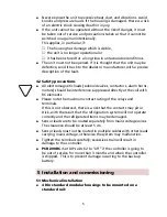
Page 5: ...ould be interference suppressed directly at the coil with RC elements I Please note the maximum contact rating of the relays and terminals If this is not observed there is a risk that the contacts may pit or stick with the result that the refrigeration system will not operate correctly and the refrigerated items may be damaged I Sensor leads are to be routed separately from mains voltage wires The...

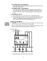
Page 6: ...nit I Mounting of sensor I Use a cable clamp to secure sensor T1 in a suitable position I Secure evaporator sensor T2 in the evaporator fin core at the point where it is suspected icing is the greatest It is advisable to use a point in the lower third of the finned evaporator 5 2 Electrical installation CAUTION The mains voltage and system frequency must be the same as the nominal values on the de...

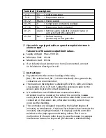
Page 7: ...tive load As a general rule contactors are recommended I The maximum tested sensor cable length is 50 m with a minimum cross section of 2 x 0 75 mm2 Solder the extension cable to the sensor cable to prevent contact resistances I It is advisable to use shielded sensor extension cables All shields must be routed at the side of the controller to one earth protective potential The extension cable shie...

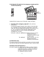
Page 8: ...bove zero do not freeze and deepfreeze installations do not thaw DIP switch 1 left Pos off bottom Setpoint value at 4 C for emergency operation Advisable for chilled storage Preset value Pos on top Setpoint value at 18 C for emergency operation Advisable for deepfreezers For PCR 300 RC only The back up battery must be switched on when the controller is started up so that the real time clock keeps ...

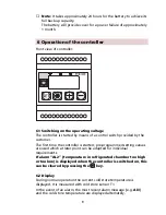
Page 9: ... first time the controller is started pre programmed setting values are used which at later point can be adapted for individual requirements If alarm AL 2 temperature in refrigerated chamber too high or too low is displayed when the controller is switched on this can be cleared by pressing the key 6 2 Display During normal operation the current cold store temperature is displayed It is measured wi...

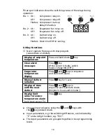
Page 10: ...temperature Clear alarm Press key messages If the sensor is faulty switch mains voltage ON OFF Evaporator Press and keys in sequence temperature and hold both down display Manual defrost Press key for 5 secs initiation Display of time Press and keys in until the next sequence and hold both down defrost Display in hours and minutes Display limit Press key value for excess temperature alarm cold sto...

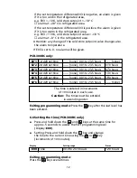
Page 11: ...erature Press and hold down the key Adjust the setpoint for the value in question using the or key Adjustment is possible within the limits of the input parameters E12 and E13 The factory setting is 4 C 6 5 Changing the cold store temperature difference defrost cycle and alarm tempera ture Access to the first programming level I Press and hold down the and keys at the same time for approx 5 second...

Page 12: ... 0 hours E2 3 3st defrost time none 00 1 to 23 5 hours 07 0 hours E2 4 4st defrost time none 00 1 to 23 5 hours 13 0 hours E2 5 5st defrost time none 00 1 to 23 5 hours 19 0 hours E2 6 6st defrost time none 00 1 to 23 5 hours none The time is entered in increments of 10 minutes in each case Caution The times must be entered in ascending order Exiting programming mode Press the key after the last l...

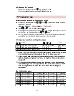
Page 13: ...0 hours E01 Cold store temp difference 1 to 20 K 2 K E02 Time between 2 defrost cycles 1 to 24 hours 8 h Once the controller has been switched on defrosting occurs for the first time at the end of the first time interval After defrosting has been initiated manually the next time defrosting takes place is after a complete time interval has elapsed If the time interval between two defrost cycles is ...

Page 14: ...2 Continuous fan operation except during defrosting 3 Fan run on If there is an undershoot in the cold store temperature the fan is switched on by evaporator sensor T2 The fan is switched off again once the desired cold store temperature is attained or exceeded E12 Minimum permissible 55 C to E13 55 C cold store temp E13 Maximum permissible E12 to 50 C 50 C cold store temp E14 Display during defro...

Page 15: ...store and evaporator sensors can be calibrated Note An additional resistance of 7 q in each case caused by the extension of the sensor cable results in a change in the temperature display by 1K How to proceed Measure the temperature at the sensor concerned with a calibrated thermometer or submerge the sensor in well mixed iced water 0 C Compare the measured temperature with the temperature display...

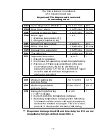
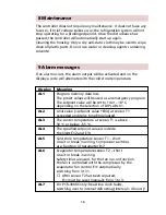
Page 16: ...an emergency program The setpoint value will be set to 4 or 18 C depending on the selection of DIP switch 1 AL2 Limit value setpoint value E03 at sensor T1 exceeded and delay time E04 elapsed AL3 The sonsor temperature at sensor T1 is above 50 C or below 55 C AL4 The specified setpoint value is outside the limits E12 and E13 AL5 Cold store temperature sensor T1 short circuit or break in wiring Com...

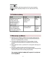
Page 17: ...ry wrong time in the event see of a power failure Section 5 3 11 Warranty conditions I Warranty is provided for a period of 12 months starting at the date the item was delivered Proof of this should be furnished in the form of a delivery note or invoice I All functional faults caused by poor workmanship or faulty materials will be repaired free of charge during the warranty period I More extensive...

Page 18: ...ata back up Non volatile memory EEPROM Clock Back up battery approx 1 month power reserve PCR 300 RC only Emergency setpoint DIP switch under display cover selection off 4 C on 18 C Sensor type PTC Number 2 sensors T1 Control signal to compressor relay T2 Control signal to defrost limitation and fan control Cable length 2 5 m Range where cable 30 C to 80 C not fixed can be used 40 C to 80 C fixed ...

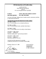
Page 19: ...1 Part 1 for the trades sector emitted interference EN 50081 2 1993 Part 1 for the industrial sector emitted interference EN 50082 1 1991 Part 1 for the trades sector immunity to interference EN 60335 1 1993 03 09 IEC 335 1 1976 ed 2 Electrical safety part 1 general requirements EN 60730 1 1992 12 09 IEC 730 1 1986 ed 1 Automatic electronic controls Full technical documentation is available Operat...

Page 20: ...Automation and Control Solutions Honeywell GmbH Hardhofweg 74821 Mosbach Germany Phone 49 0 62 61 81 475 Fax 49 0 62 61 81 461 E Mail Cooling Mosbach honeywell com www honeywell cooling com ...

Reviews: