Pegasus High Temperature Controller Shortform
ZA0937-ZBC Issue E
May18, 2007.
Honeywell Refrigeration Control, Newhouse Industrial Estate, Motherwell, ML1 5SB.
Tel: 01698 481698, Fax: 01698 481699, Web:
www.refrigeration.europe.honeywell.com
Overview
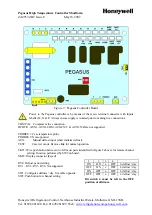
Pegasus (Figure 2) is a refrigeration controller
used to switch refrigeration ON, if the operating
temperature (4
o
C) exceeds the running
temperature setting, and OFF if the operating
temperature falls below the running temperature
setting by 3
o
C. Four bit switches located on the
controller board control the frequency defrost. A
display (Figure 1), connected to the controller can
show either the operating temperature or one of
the following four messages:
1.
dF: the controller is in defrost
2.
Flashing between dF and operating
temperature: controller is recovering from
defrost
3.
Flashing between PF1 and 30
o
C: probe failure
4.
Flashing between AL and operating
temperature: over temperature alarm
The maximum defrost time is set by adjusting
RV4 and viewed whilst in the setting mode. Table
1 below, describes these settings:
Channel
ID
Reading
Pot
Range
Pr
Case
temperature
probe
-30
o
C to
+30
o
C
Ch4
Maximum
defrost
time
RV4
10 to 40
minutes
Table 1: Pegasus Control Settings
Defrost Settings
The controller initiates defrosts at intervals set on
the defrost frequency switches (Table 2).
The compressor is held OFF for the maximum
defrost period, during defrost.
After defrost the controller enters the recovery
state. The compressor is cycled as normal for 15
minutes. During recovery the display flashes
between the operating temperature and “dF”.
Setting Mode
Setting mode is selected using the channel setting
push button (or an optional remote channel select
button) on the controller board. Hold down the
button to view the termination time (Ch4) on the
display (Table 1). Release the button to see the
value appropriate to that channel. Adjust the
setting using a screwdriver whilst the appropriate
channel is selected. The display automatically
reverts to normal after a period of 30 seconds.
Probes
Pegasus is equipped with two inputs; P1 and
AUX. The case temperature probe connects to P1
and the manual defrost initiation switch to AUX.
Power Up
The fans are powered continuously from a supply
on the board. The compressor is held OFF for two
minutes after power up.
Hold down the channel select button whilst the
case is switched on to override the two minute
delay period and start the compressor immediately
on power up.
Case Test Mode
Put the controller into test mode by connecting the
link on LK2 (Figure 2). Bit switch 3 now controls
the relay output. The display shows bC followed
by the software version.
Over Temperature Alarm
The over temperature alarm level is set at 10
o
C
with a 30 minute alarm delay. The over
temperature alarm level and the alarm delay
cannot be altered. The over temperature alarm is
disabled during defrost.
Compressor Minimum On/Off Time
The minimum ON/OFF time ensures that when
the compressor switches ON/OFF, it remains
ON/OFF, for a minimum period of two minutes.
Probe Fault
If a probe fault occurs on P1, the display flashes
between PF1 and 30
o
C. The compressor switches
ON and then OFF continuously , every 8 minutes.
Connecting a Display
Connect the display to your Pegasus controller
using the inf ormation shown in Figures 1 and 2.
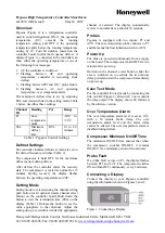
Figure 1: Connecting a Display


