Pegasus High Temperature Controller Shortform
ZA0937-ZBC Issue E
May18, 2007.
Honeywell Refrigeration Control, Newhouse Industrial Estate, Motherwell, ML1 5SB.
Tel: 01698 481698, Fax: 01698 481699, Web:
www.refrigeration.europe.honeywell.com
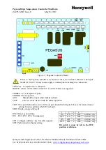
Figure 2 : Pegasus Controller Board
Power to the Pegasus controller is by means of the screw terminal connector with inputs
labelled L, N & E. Always ensure supply is isolated prior to making live connections.
COMP (L): Compressor live connection.
DF HTR , AUX1, AUX2 COM, AUX2 N/C & AUX2 N/O are not supported.
PROBES 1: Case temperature probe
PROBES 2: Not supported
AUX: Manual defrost input (short initiates defrost).
TEST: Case test mode. Remove link for normal operation.
SKT1: Wire push button between two left most pads (identified in Figure 2 above) for remote channel
setting. Function performed by SW2 on board.
SKT2: Display connector (keyed)
RV4: Defrost period setting
RV1 – RV3, RV5, RV6: Not supported
SW1: Configures defrosts / day. See table opposite:
SW2: Push button for channel setting.
Bit switch 4 must be left in the OFF
position at all times.
1
2
3
4
ON
ON
x
OFF
6 defrost / day
OFF
ON
x
OFF
4 defrost / day
ON
OFF
x
OFF
3 defrost / day
OFF
OFF
x
OFF
2 defrost / day


